

Battery Energy Storage System (BESS): Complete Guide to Design, Components, Applications and Safety
A battery energy storage system (BESS) stores electrical energy in rechargeable batteries and returns it through power conversion equipment when the site or grid needs it. A complete BESS normally combines battery cells and racks, a battery management system (BMS), a power conversion system (PCS), an energy management system (EMS), thermal management, protection, fire detection or mitigation, metering and communications. Project success depends on matching power, energy, duty cycle, interconnection and safety requirements-not simply selecting a battery capacity.
For an EPC contractor or system integrator, a BESS is a coordinated electrical and controls plant. For a project developer, it is an asset whose value depends on dispatch rules, availability, degradation and market access. For procurement teams, it is a multi-supplier package whose warranties, interfaces, test evidence and service obligations must align. This guide provides a common technical framework for all four perspectives.
For projects requiring scalable behind-the-meter storage, review SINELINK's commercial and industrial energy storage systems to compare the available platform categories.
Key takeaways for project teams
- Define the use case and operating profile before choosing kW or kWh.
- Treat PCS, BMS, EMS, protection, thermal management and communications as one integrated system.
- Evaluate usable energy at the required conditions, not nameplate capacity alone.
- Confirm local grid, electrical, building and fire requirements with the relevant authority having jurisdiction (AHJ).
- Make safety evidence, interface ownership, warranties and acceptance tests explicit in procurement documents.
On This Page
- What Is a Battery Energy Storage System (BESS)?
- How Does a Battery Energy Storage System Work?
- Core BESS Components: Battery, BMS, PCS, EMS and Balance of System
- BESS Design and Sizing: From Use Case to Guaranteed Performance
- Battery Energy Storage System Applications for Commercial, Industrial and Grid Projects
- BESS Safety: Standards, Thermal Runaway and Project Risk Controls
- Cabinet, Containerized and Medium-Voltage BESS Architectures
- BESS Procurement Checklist for EPCs, Developers and Integrators
- BESS Project Lifecycle: Engineering, Testing, Commissioning and O&M
- Common BESS design and procurement mistakes
- Frequently Asked Questions About Battery Energy Storage Systems
- Conclusion
What Is a Battery Energy Storage System (BESS)?
A battery energy storage system is an assembly that receives electrical energy, converts and stores it electrochemically, and later supplies electrical energy to a load or grid. Stationary BESS projects range from compact behind-the-meter systems to cabinet, container and power-block installations connected at low or medium voltage.
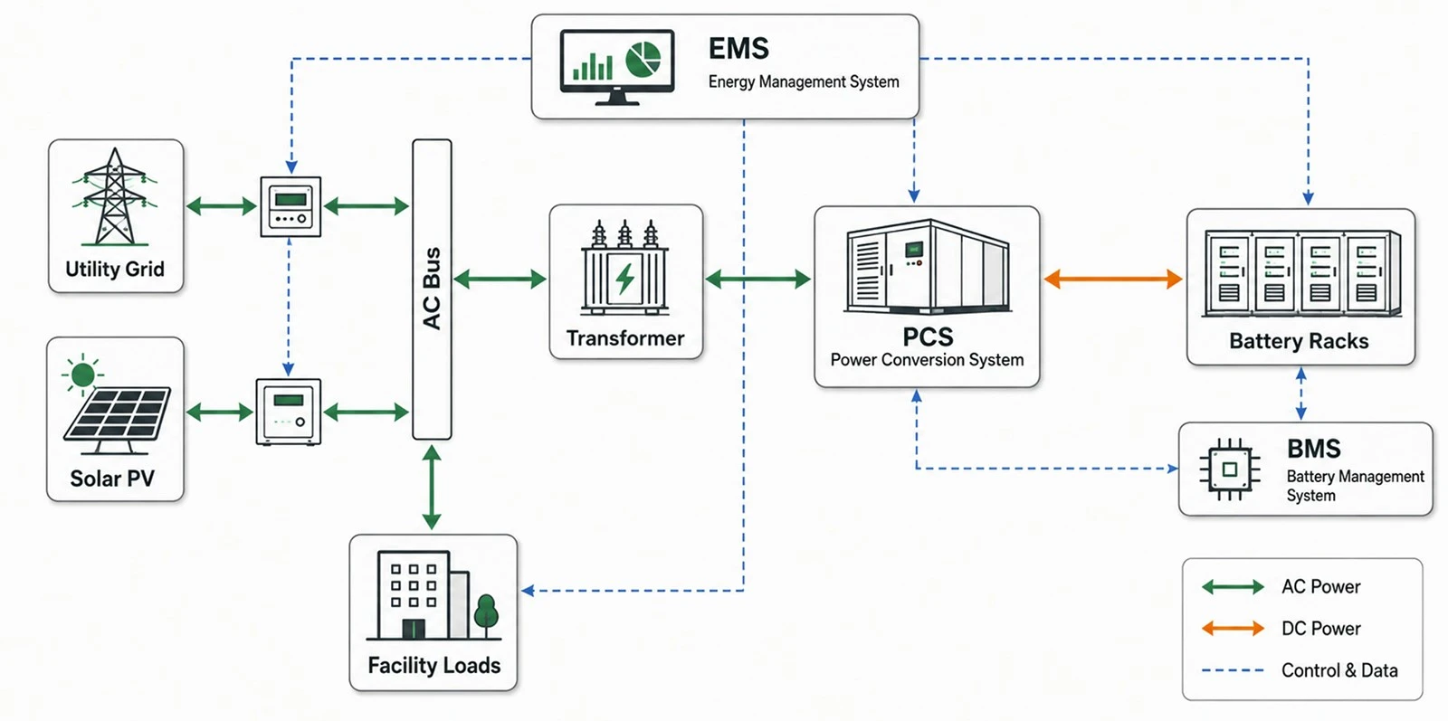
BESS system overview from grid to battery and load
A battery energy storage system is an assembly that receives electrical energy, converts and stores it electrochemically, and later supplies electrical energy to a load or grid. Stationary BESS projects range from compact behind-the-meter systems to cabinet, container and power-block installations connected at low or medium voltage.
The battery is only one subsystem. The delivered plant also needs bidirectional conversion, control, protection, auxiliary power, communications and a safe physical installation. This distinction matters during tendering: a battery rack price cannot be compared directly with a complete, commissioned BESS price.
BESS, ESS and battery bank: what is the difference?
|
Term |
Practical meaning |
Procurement implication |
|
ESS |
Broad category covering technologies that store energy, including batteries, thermal, mechanical and other methods. |
Confirm the storage technology and full system boundary. |
|
BESS |
An energy storage system whose storage medium is rechargeable batteries. |
Specify cells through grid/load interface, controls and auxiliaries. |
|
Battery bank / rack |
Battery modules connected to provide DC voltage and energy. |
Not a complete BESS; PCS, controls, protection and balance of system may be excluded. |
|
Power block |
A repeatable grouping of batteries, PCS and often transformer/switchgear. |
Useful for modular utility or large C&I design; confirm exact included scope. |
AC-coupled and DC-coupled configurations
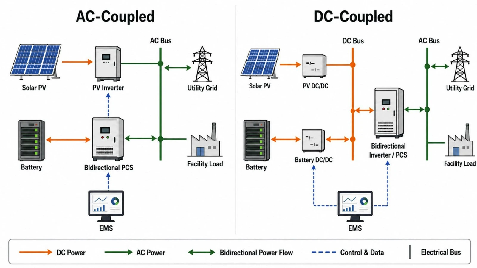
AC-coupled VS DC-coupled
In an AC-coupled system, the battery has its own PCS and connects on the AC side. This can simplify retrofit work and allow independent operation of PV and storage. In a DC-coupled solar-plus-storage system, PV and batteries share a DC-side architecture before conversion to AC. This may reduce conversion steps for stored solar energy, but requires careful voltage-window, protection and controls coordination..
AC coupling is often attractive for retrofits and flexible independent operation; DC coupling can be attractive when capturing solar energy on the DC side is central to the design. Neither is universally better. The correct choice depends on existing assets, interconnection limits, clipping or curtailment opportunity, operating modes, controls and lifecycle economics.
How Does a Battery Energy Storage System Work?
During charging, the PCS converts AC power from the grid or onsite generation into DC power suitable for the battery. The BMS supervises cell and module conditions and communicates operating limits. The EMS decides when and how much to charge or discharge, based on the use case, tariffs, forecasts, site load, grid commands and reserve requirements. During discharge, the PCS converts battery DC power back to controlled AC power.
- Measure: meters and sensors capture load, generation, voltage, frequency, temperatures and system status.
- Decide: the EMS applies the dispatch objective and operating constraints.
- Authorize: the BMS calculates safe charge and discharge limits; protection logic checks permissives.
- Convert: the PCS controls bidirectional power flow and grid synchronization.
- Verify: monitoring records performance, alarms, state of charge and event data for operations and warranty evidence.
Power, energy and duration
Power (kW or MW) is the rate at which the system charges or discharges. Energy (kWh or MWh) is the amount stored or delivered. Duration is commonly expressed as energy divided by rated discharge power. A 1 MW / 2 MWh system is nominally a two-hour system at rated power, before applying usable-state-of-charge limits, conversion losses, temperature effects, auxiliary consumption and degradation allowances.
BESS duration (hours) = usable energy (kWh) ÷ discharge power (kW). Use usable, warranted energy at the defined operating conditions-not only the nameplate energy-to assess whether the required discharge period can be met.
Core BESS Components: Battery, BMS, PCS, EMS and Balance of System
For DC and AC conductor engineering, use the BESS cable selection guide to check voltage, ampacity, voltage drop, fault withstand and termination compatibility.
For a dedicated component-by-component explanation, read BESS components explained covering battery hardware, BMS, PCS, EMS, thermal systems and balance of system.
|
Subsystem |
Primary function |
Key specification questions |
|
Cells, modules and racks |
Store DC energy. |
Chemistry; usable energy; voltage window; temperature range; degradation; traceability. |
|
BMS |
Monitors cells/modules, estimates SOC/SOH, balances cells and enforces battery limits. |
Hierarchy; sampling; fault logic; cybersecurity; PCS interface; data retention. |
|
PCS / inverter |
Converts power bidirectionally and controls AC output. |
Power rating; overload; efficiency map; grid code; fault ride-through; harmonics; reactive power. |
|
EMS / plant controller |
Optimizes dispatch and coordinates site/grid objectives. |
Algorithms; metering; forecasts; external protocols; fail-safe modes; API; ownership of logic. |
|
Thermal management |
Maintains components within operating temperature limits. |
Air/liquid cooling; redundancy; ambient design; parasitic load; leak detection; maintenance. |
|
Protection and switchgear |
Detects and isolates electrical faults. |
DC/AC isolation; coordination; arc-flash; grounding; insulation monitoring; emergency stop. |
|
Fire and gas safety |
Detects abnormal conditions and supports risk mitigation. |
Applicable code; detection; ventilation; off-gas strategy; propagation test evidence; emergency plan. |
|
Transformer and MV equipment |
Matches grid voltage and provides switching/protection. |
Vector group; impedance; losses; harmonics; relays; utility requirements. |
|
SCADA and communications |
Provides monitoring, commands, alarms and records. |
Protocols; time synchronization; remote access; cybersecurity; data ownership; redundancy. |
|
Auxiliary systems |
Power cooling, controls, lighting and safety systems. |
Station service source; backup; black-start needs; auxiliary energy accounting. |
For mainstream high-voltage C&I integration, review the 1000V high-voltage battery system platform and confirm its operating window against the selected PCS.
For larger 1500V-class architectures, compare the 1331V high-voltage battery platform with project voltage, current and protection requirements.
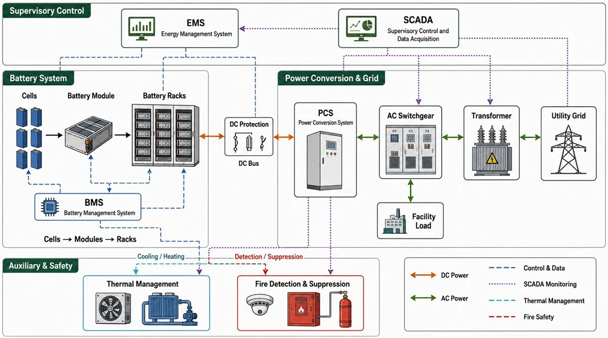
Battery chemistry selection
Chemistry selection should consider safety behavior, energy density, power capability, temperature range, cycle and calendar aging, supply chain, service experience, transport requirements and end-of-life plans. Lithium iron phosphate (LFP) is widely used in stationary storage, but chemistry name alone does not establish system safety or life. Cell quality, mechanical design, thermal management, BMS limits, manufacturing controls and installation conditions remain material.
Procurement documents should request evidence at the cell, module, rack and system levels. Avoid converting a test report or certificate into a blanket claim that every project configuration is compliant; the installed configuration, jurisdiction and applicable edition matter.
BESS Design and Sizing: From Use Case to Guaranteed Performance
For the full calculation workflow, use the BESS sizing guide to convert interval data, power, duration, losses and degradation into guaranteed kW and kWh.
Start BESS sizing with a time-series profile and a defined operating objective. Determine required power from the highest controlled demand or grid service, determine usable energy from duration and dispatch, then add allowances for operating SOC limits, conversion losses, auxiliary loads, temperature, availability and degradation. Validate the result through simulation and a guaranteed-performance schedule.
Step 1: define the use case and operating envelope
A bankable design begins with a written operating philosophy. State whether the system will perform peak shaving, time-of-use shifting, solar self-consumption, backup, microgrid support, curtailment capture, capacity service or ancillary services. If revenues are stacked, define priority and conflicts. For example, a backup reserve reduces energy available for daily arbitrage.
- Site load and generation data at a suitable interval, preferably covering a representative year.
- Tariff, demand-charge rules, export limits and market dispatch requirements.
- Critical-load power, starting currents and required backup duration.
- Grid connection voltage, short-circuit level, utility protection and power-quality requirements.
- Ambient temperature, altitude, humidity, dust, corrosion, flooding, seismic and acoustic constraints.
- Required operating life, availability, warranty throughput and end-of-life capacity.
Step 2: calculate power and usable energy
For peak shaving, power is influenced by the difference between the uncontrolled facility peak and the target import limit; energy is the area between the load curve and target during the controlled period. For backup, power must support coincident critical loads and transient demands; energy must cover the required autonomy, accounting for load evolution and restart strategy.
|
Sizing item |
Conceptual expression |
Engineering note |
|
Nominal duration |
Usable energy ÷ discharge power |
State the reference power and operating conditions. |
|
Required delivered energy |
Load or service energy over the dispatch window |
Use time-series data; include recovery/recharge constraints. |
|
Installed energy |
Required delivered energy ÷ combined availability/efficiency/usable-fraction factors |
Apply factors transparently; do not hide all margin in one percentage. |
|
End-of-life requirement |
Beginning-of-life capacity adjusted for warranted degradation or augmentation |
Define year, cycles/throughput, temperature and test method. |
|
PCS power |
Continuous and short-duration site/service requirement |
Check ambient derating, reactive power, overload and grid-voltage range. |
Step 3: model losses, degradation and availability
Round-trip efficiency is not a single universal number. It depends on power level, voltage, temperature, auxiliaries, metering boundary and whether transformer losses are included. Ask for an efficiency curve and define the guaranteed measurement boundary. Model calendar aging and cycling separately, using the intended SOC window, depth of discharge, temperature and throughput. For long-life projects, compare oversizing with planned augmentation.
Availability assumptions should distinguish scheduled maintenance, forced outages, grid outages and external curtailment. Define whether a partial-power condition counts as available. These definitions belong in the performance guarantee, not only in the financial model.
Step 4: confirm electrical and controls integration
Verify the battery voltage window against the PCS DC operating range across SOC and temperature. Check maximum current, cable and busbar ratings, DC protection, grounding method and insulation monitoring. On the AC side, complete load flow, short-circuit, protection coordination, harmonic, grounding and arc-flash studies as applicable. The EMS, PCS and BMS responsibility matrix should identify every command, limit, alarm, permissive and fallback state.
Projects requiring active interaction with the utility can review SINELINK's grid-connected battery storage solution as a starting point for technical discussion.
For megawatt-scale industrial connections, a medium-voltage industrial ESS may reduce long low-voltage cable runs, subject to utility and protection studies.
Battery Energy Storage System Applications for Commercial, Industrial and Grid Projects
For a facility-focused application framework, continue to the C&I BESS practical guide.
Peak shaving and demand management
The detailed control and calculation method is covered in the BESS peak shaving guide.
A behind-the-meter BESS can discharge when facility demand approaches a contracted or economic threshold. The controller must anticipate peaks, preserve sufficient SOC and avoid creating a later rebound peak while recharging. Feasibility depends on the tariff structure and the width, frequency and predictability of load peaks.
For demand-charge control applications, review the peak shaving battery system and validate the configuration against the facility load profile.
Time-of-use shifting and energy arbitrage
The system charges during lower-cost periods and discharges during higher-cost periods. Net value depends on the price spread after conversion losses, auxiliary energy, degradation cost, demand impacts and export constraints. Financial models should use realistic dispatch limits and warranty terms rather than perfect-foresight assumptions.
Solar self-consumption, clipping and curtailment capture
Coupling and integrated controls are explained in the solar-plus-storage guide.
Storage can move surplus solar production to later demand periods, maintain export below an interconnection limit, or capture energy that would otherwise be curtailed. The design should model seasonal PV production, facility load, export rules, DC/AC coupling, recharge opportunity and the competing value of reserve capacity.
Backup power and microgrids
Backup design requires more than adequate kWh. The system must establish or follow a voltage and frequency reference, isolate safely from the utility, start or support large loads and coordinate with generators and renewable sources. Confirm black-start capability, transfer sequence, load shedding and restart logic through functional tests.
Grid services and network support
Depending on market rules and interconnection approval, BESS can provide frequency response, reactive power, ramp control, capacity or congestion relief. The commercial contract should align response accuracy, telemetry, availability, state-of-charge management and performance penalties with the technical controls.
BESS Safety: Standards, Thermal Runaway and Project Risk Controls
For a dedicated hazard and standards review, use the BESS safety guide.
BESS safety is achieved through layered risk control: suitable cells and system architecture; validated BMS limits; electrical protection and isolation; thermal management; fault and off-gas detection; fire and explosion risk assessment; tested installation configuration; emergency planning; commissioning; and disciplined operation and maintenance. A certificate or suppression device alone is not a complete safety strategy.
Primary hazard categories
- Electrical: shock, arc flash, short circuit, insulation failure, grounding faults and stored DC energy.
- Thermal and fire: overheating, internal cell failure, thermal runaway and propagation.
- Gas and explosion: flammable or toxic vent gases, accumulation and ignition.
- Mechanical and environmental: impact, seismic loads, flooding, water ingress, corrosion and extreme temperature.
- Controls and cyber: unsafe commands, communication loss, sensor failure and unauthorized remote access.
- Lifecycle: transport damage, installation error, maintenance, damaged equipment, stranded energy and decommissioning.
Standards and codes: how to use them correctly
|
Reference |
Role in a project |
Important limitation |
|
IEC 62933-5-1:2024 |
General safety considerations, hazard identification, risk assessment and mitigation for grid-integrated EES. |
Apply with technology-specific and local requirements. |
|
IEC 62933-5-2:2020 |
Safety requirements for grid-integrated electrochemical EES over the lifecycle. |
Confirm current edition and project applicability. |
|
IEC 62619 |
Safety requirements for industrial secondary lithium cells and batteries. |
Cell/battery scope does not replace whole-system or installation review. |
|
UL 9540 |
Safety standard for energy storage systems and equipment. |
Listing scope and exact configuration matter. |
|
UL 9540A |
Test method evaluating thermal-runaway fire propagation behavior. |
It is a test method, not a standalone system certification or universal installation approval. |
|
NFPA 855 |
Installation standard for stationary ESS in the United States. |
Adoption and amendments vary; coordinate with the AHJ and applicable building/fire/electrical codes. |
|
IEEE 1547 / local grid code |
Interconnection and interoperability requirements for distributed energy resources. |
The applicable jurisdiction and utility requirements govern. |
|
UN Manual of Tests and Criteria, 38.3 |
Transport testing for lithium cells and batteries. |
Transport compliance is not proof of stationary installation safety. |
Source note: verify the adopted edition, national deviations and project-specific requirements at the time of design. The AHJ, utility, insurer and fire service may require documentation beyond the equipment certificate.
Thermal runaway: prevention, detection and mitigation
Thermal runaway is a self-accelerating heat-producing failure process. Project teams should focus first on preventing abnormal conditions and limiting propagation, then on detection, ventilation, separation, emergency response and consequence mitigation. The correct strategy depends on chemistry, enclosure, energy capacity, site arrangement and jurisdiction.
- Prevention: qualified cells, manufacturing controls, conservative electrical limits, thermal uniformity and fault isolation.
- Early detection: cell voltage and temperature analytics, smoke/heat detection and, where justified, off-gas detection.
- Propagation control: module and rack barriers, spacing, enclosure design and evidence from representative testing.
- Consequence management: ventilation or deflagration controls where required, drainage/containment considerations, access and emergency procedures.
- Recovery: isolation, monitoring for reignition, damaged-equipment handling and a documented return-to-service process.
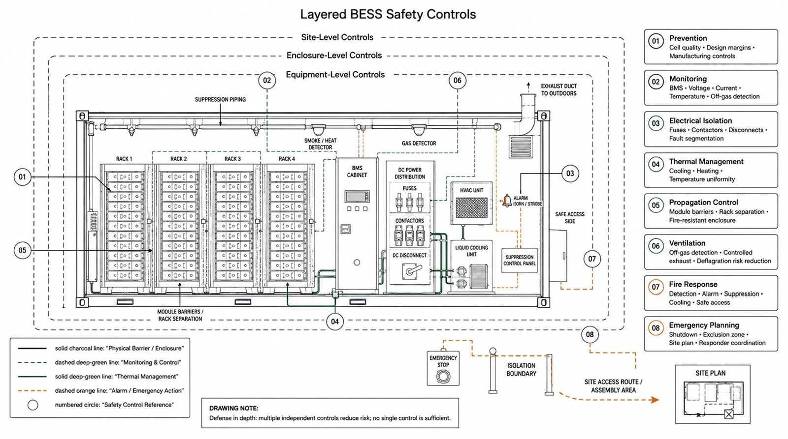
Site planning and emergency response
Layout must preserve equipment access, egress, working clearances, firefighting access and required separation. Evaluate nearby buildings, property lines, occupied areas, air intakes, flood levels and vehicle impact. Before energization, provide site plans, isolation points, hazards, contact information and response procedures to relevant responders. The emergency plan should address shutdown, damaged equipment, stranded energy and possible reignition.
Cabinet, Containerized and Medium-Voltage BESS Architectures
|
Architecture |
Typical strengths |
Key trade-offs |
|
Outdoor cabinet |
Modular deployment; suitable for many C&I sites; incremental expansion. |
More field interconnection points; spacing and service access; site-level integration. |
|
Containerized BESS |
Factory integration; repeatable power blocks; suited to larger projects. |
Transport and lifting; internal access strategy; ventilation/fire analysis; replacement logistics. |
|
Indoor battery room |
Can use existing building infrastructure and controlled environment. |
Building/fire code, ventilation, egress, structural load and retrofit constraints. |
|
Medium-voltage integrated block |
Reduces long low-voltage cable runs and supports MW-scale connection. |
Protection, transformer/switchgear interface, utility coordination and specialist maintenance. |
|
Liquid-cooled battery cabinet |
Tighter temperature control and higher packaging density in many designs. |
Cooling-loop complexity, leak detection, pump energy and service capability. |
Sites with high ambient temperatures or dense packaging requirements can evaluate a liquid-cooled industrial battery cabinet while confirming cooling redundancy and service needs.
For smaller household applications, see SINELINK's residential energy solutions rather than applying a C&I architecture directly.
BESS Procurement Checklist for EPCs, Developers and Integrators
A comparable BESS tender defines the system boundary, operating profile, guaranteed power and usable energy, degradation basis, availability definition, efficiency measurement boundary, safety and test evidence, interface responsibilities, acceptance tests, warranty remedies, spares, service response and end-of-life obligations.
Minimum request-for-proposal package
- Site and application data: single-line diagram, load/PV profile, grid data, environment and civil constraints.
- Functional specification: use cases, operating modes, priority logic, reserve, response time and remote-control requirements.
- Guaranteed-performance schedule: power, usable energy, efficiency, auxiliary load, availability, degradation and noise at defined conditions.
- Compliance matrix: applicable standards, codes, certificates, test reports and project-specific deviations.
- Scope matrix: batteries, PCS, transformer, switchgear, EMS/SCADA, cabling, civil works, installation, commissioning and utility tests.
- Lifecycle services: training, spares, software support, cybersecurity updates, preventive maintenance, response times and augmentation.
Documents to request before award
|
Document |
Why it matters |
Review owner |
|
Technical datasheets and performance curves |
Confirms ratings across voltage, temperature and loading. |
Electrical + storage engineer |
|
Single-line and interface drawings |
Defines equipment boundary and interconnections. |
EPC / integrator |
|
Certificates and complete test reports |
Confirms scope, model and configuration behind compliance claims. |
Compliance / fire engineer |
|
Hazard analysis and safety concept |
Shows identified hazards, controls and residual risks. |
Owner's engineer / AHJ interface |
|
EMS/BMS/PCS signal list |
Prevents gaps in controls, alarms and limits. |
Controls engineer |
|
Warranty and performance guarantee |
Aligns remedies with the financial model and duty cycle. |
Developer + legal + engineering |
|
FAT/SAT and commissioning plan |
Makes acceptance measurable before delivery. |
EPC + owner |
|
O&M, emergency and decommissioning plans |
Supports safe lifecycle operation and budgeting. |
Asset manager / HSE |
Questions that expose hidden commercial risk
- At what metering boundary and operating conditions are power, energy and efficiency guaranteed?
- What operating profile, temperature and throughput assumptions support the degradation warranty?
- Which components and software versions are included in the certification or test report?
- Who owns integration between BMS, PCS, EMS, plant controller and utility SCADA?
- How are partial outages, auxiliary consumption and scheduled maintenance treated in availability?
- What happens if the required replacement cell, module, inverter or controller is discontinued?
- Which cybersecurity controls, remote-access methods, data rights and update obligations apply?
- What field tests demonstrate each operating mode and safety interlock before acceptance?
Planning a C&I or industrial storage project? Send SINELINK your load profile, target power and duration, grid voltage, site conditions and required standards. Our team can help structure a preliminary system configuration and documentation checklist.
BESS Project Lifecycle: Engineering, Testing, Commissioning and O&M
- Feasibility: validate the use case, data quality, site constraints, interconnection path and commercial value.
- Concept design: select coupling and architecture, establish kW/kWh, define system boundary and develop the safety concept.
- Detailed engineering: complete electrical, civil, structural, thermal, fire, controls, protection and communications design.
- Factory testing: verify equipment configuration, communications, protection, alarms and representative operating modes.
- Site installation: inspect transport condition, civil works, cabling, grounding, labeling, clearances and environmental sealing.
- Commissioning and acceptance: energize in controlled stages, test interfaces and modes, record baseline capacity/performance and train operators.
- Operations and maintenance: monitor trends, manage firmware and cybersecurity, test safety systems, maintain auxiliaries and preserve warranty evidence.
- Augmentation and end of life: plan capacity additions, reuse/recycling, isolation, transport and decommissioning before the asset reaches retirement.
Common BESS design and procurement mistakes
- Sizing from a single monthly peak instead of interval load data and an operating simulation.
- Comparing nameplate kWh without aligning usable-energy conditions and degradation assumptions.
- Using one round-trip-efficiency number without defining the metering boundary and auxiliary loads.
- Assuming a component certificate proves the installed system and site comply with all requirements.
- Leaving BMS–PCS–EMS responsibility and failure-state behavior undefined.
- Treating fire suppression as the entire thermal-runaway strategy.
- Ignoring recharge time, reserve conflicts and rebound peaks in stacked-use cases.
- Accepting marketing case studies, performance claims or service commitments without traceable evidence.
Frequently Asked Questions About Battery Energy Storage Systems
Q: What is the main purpose of a BESS?
A BESS shifts electrical energy in time and controls power flow. Depending on the design, it can reduce demand peaks, increase solar self-consumption, provide backup power, manage export limits or support grid services.
Q: What are the main components of a BESS?
A complete BESS typically includes battery cells/modules/racks, BMS, PCS, EMS or plant controller, thermal management, electrical protection, fire and gas safety systems, metering, communications and balance-of-system equipment such as transformer and switchgear.
Q: How do you size a battery energy storage system?
Define the use case, analyze time-series load and generation, calculate the required power and usable energy, then model SOC limits, conversion losses, auxiliaries, temperature, degradation, availability and recharge constraints. Validate the result with a dispatch simulation and performance guarantee.
Q: What is the difference between kW and kWh in BESS design?
kW measures charge or discharge power; kWh measures stored or delivered energy. Dividing usable kWh by kW gives nominal duration in hours at that power.
Q: What is BESS round-trip efficiency?
Round-trip efficiency is energy delivered divided by energy used to charge over a defined cycle and measurement boundary. The value changes with power, temperature, auxiliaries and whether PCS and transformer losses are included.
Q: What does the BMS do?
The BMS monitors cell and module conditions, estimates state of charge and health, balances cells, calculates allowable charge/discharge limits, records faults and initiates protective actions.
Q: What is the difference between a PCS and an EMS?
The PCS converts power between AC and DC and controls electrical output. The EMS decides when and how the system should operate based on site, market and grid objectives, while respecting equipment limits.
Q: Is LFP battery chemistry inherently safe?
LFP has characteristics that can be advantageous for stationary storage, but chemistry alone does not make an installation safe. Cell quality, BMS limits, thermal design, electrical protection, propagation behavior, installation and emergency planning all matter.
Q: What do UL 9540 and UL 9540A mean?
UL 9540 addresses safety of energy storage systems and equipment. UL 9540A is a test method used to evaluate thermal-runaway fire propagation behavior. Test scope, configuration, applicable code and AHJ acceptance must be checked for each project.
Q: How long does a BESS last?
Service life depends on chemistry, temperature, SOC, depth of discharge, throughput, calendar time, maintenance and augmentation. Evaluate a warranted capacity trajectory under the intended duty cycle rather than relying on a single cycle-life number.
Q: Can a BESS provide backup power?
Yes, if the PCS and controls support the required islanding or grid-forming behavior, transfer scheme, critical-load power, starting currents, duration, grounding and protection. Not every grid-tied BESS is designed for backup operation.
Q: What information should be included in a BESS RFQ?
Include interval load/generation data, use cases, grid and site conditions, required kW/kWh, operating modes, standards, system boundary, performance guarantees, safety evidence, interface matrix, FAT/SAT, warranty and service requirements.
Need a project-specific BESS configuration? Share your application, interval load or generation profile, grid voltage, target power and duration, installation environment and compliance market.
To continue product evaluation, view SINELINK's energy storage and solar product portfolio and request controlled technical documentation for the shortlisted equipment.
Conclusion
A successful battery energy storage system is not selected from a kWh figure alone. It is engineered around a use case, duty cycle, electrical interface, control philosophy, safety case, lifecycle plan and measurable commercial obligations. EPCs, integrators, developers and procurement teams can reduce project risk by defining these requirements early and evaluating every supplier against the same evidence-based framework.