

BESS CABLE ENGINEERING
SELECTION • SIZING • SAFETY
BESS Cable Selection Guide: DC Power Cables, Sizing, Voltage and Safety
QUICK ANSWER
Select a BESS cable by the circuit's maximum operating voltage, continuous and fault current, corrected ampacity, allowable voltage drop, conductor and insulation temperature, installation method, environmental exposure, short-circuit withstand, bend radius, terminal and gland compatibility, fire-performance requirements, and the applicable electrical code. Cable cross-section alone does not establish suitability.
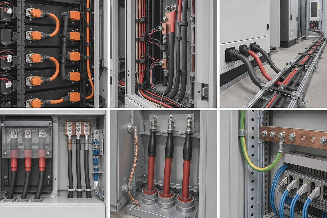
Battery energy storage systems contain several different cable duties: cell and module interconnects, rack-to-combiner or DC-bus connections, battery-to-PCS feeders, AC output cables, protective-earth conductors, auxiliary circuits and communication wiring. Each duty has different electrical, thermal, mechanical and installation constraints. A cable described only as "battery cable" or "1500 V cable" is therefore not a complete specification.
For the overall project framework, begin with the complete battery energy storage system guide covering design, safety, applications and procurement.
To understand where each cable sits in the system, review BESS components explained before preparing the cable schedule.
For the charging and discharging power path, see how a battery energy storage system works and trace the DC and AC measurement boundaries.
On This Page
- Which cables are used in a BESS?
- Step 1: define maximum system voltage
- Step 2: calculate design current and corrected ampacity
- Step 3: check voltage drop and power loss
- Step 4: verify short-circuit withstand and protection
- Step 5: select conductor, insulation and sheath
- Step 6: confirm terminal, connector and gland compatibility
- Step 7: design routing and installation
- BESS cable standards and compliance
- Procurement documentation checklist
- Common BESS cable specification mistakes
- Frequently asked questions
- Conclusion
Which cables are used in a BESS?
Facility architecture and cable duties can be cross-checked in the C&I BESS practical guide.
QUICK ANSWER
A typical BESS uses flexible DC battery cables or busbars inside racks, higher-current DC feeders between racks/combiner and PCS, AC power cables from PCS to switchgear or transformer, protective-earth conductors, auxiliary power cables, and screened or fiber communication cables. Exact construction and approvals depend on voltage, location, movement, enclosure and market requirements.
|
Cable duty |
Typical connection |
Critical checks |
|
Module/rack interconnect |
Modules, trays, rack busbars or disconnects |
Flexibility, current, temperature, terminal system, touch protection and service replacement. |
|
Rack/combiner DC feeder |
Rack output to combiner or DC distribution |
Voltage class, ampacity, fault current, parallel paths, routing and identification. |
|
Battery-to-PCS DC cable |
DC bus or combiner to PCS |
Voltage drop, short-circuit withstand, polarity, insulation monitoring and termination. |
|
PCS AC output |
PCS to LV switchboard or transformer |
AC ampacity, harmonics, grouping, protection, grounding and grid code. |
|
Protective earth |
Cabinets, PCS, transformer and structures |
Fault current, bonding continuity, corrosion and local code. |
|
Auxiliary/control |
HVAC, pumps, sensors and safety systems |
Segregation, EMC, fire survival where required and backup supply. |
|
Communications |
BMS, PCS, EMS, meters and SCADA |
Protocol, shielding/fiber, bend radius, segregation, cybersecurity and redundancy. |
SINELINK's current cable category can be reviewed under energy storage cables; confirm the exact product page, datasheet and certification scope before publication or procurement.
Step 1: define maximum system voltage
The cable voltage rating must cover the circuit's maximum calculated voltage, including charger or PCS limits, battery series configuration, charging state, temperature effects and transients addressed by the design. The lowest-rated element among cable, connector, terminal, fuse, contactor, disconnect and gland can limit the circuit.
- Record nominal, minimum and maximum DC voltage-not one nominal number.
- Confirm conductor-to-conductor and conductor-to-earth rating conventions.
- Check insulation coordination, creepage/clearance at terminations and altitude effects where applicable.
- Use components evaluated for DC service; AC and DC interruption behavior are not interchangeable.
For a common C&I voltage architecture, compare the cable schedule with the 1000V high-voltage battery system operating range and maximum current.
For 1500V-class projects, coordinate insulation and termination requirements with the 1331V high-voltage battery platform rather than assuming a lower-voltage cable design can be reused.
Step 2: calculate design current and corrected ampacity
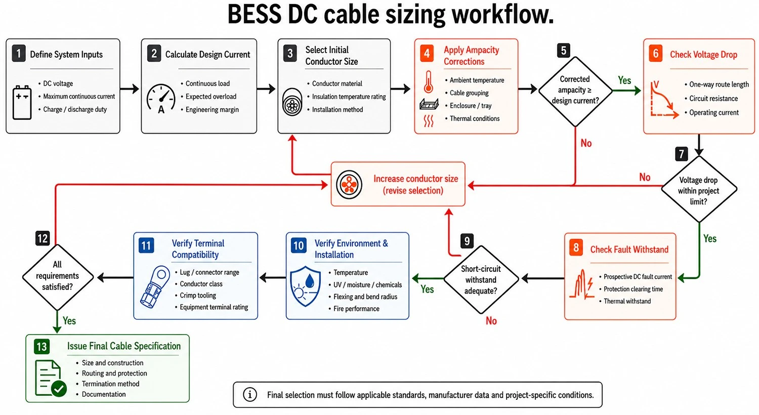
The system duty that drives cable current should come from the BESS sizing guide and the approved charge/discharge operating profile.
Cable ampacity depends on conductor size and material, insulation temperature rating, ambient temperature, enclosure temperature, grouping, conduit or tray arrangement, ventilation, duty cycle and terminal temperature limits. The design current should reflect maximum continuous charge/discharge, overload profile, parallel paths and any code-required factors.
KEY TAKEAWAY
Do not select a BESS cable from a generic online ampacity table. Tables use specific ambient, conductor temperature, grouping and installation assumptions. Final ampacity must follow the applicable code, approved cable data and actual route.
Step 3: check voltage drop and power loss
For a two-conductor DC circuit, a preliminary voltage-drop estimate may use ΔV = 2 × L × I × R, where L is one-way length and R is conductor resistance per unit length at the relevant operating temperature. Manufacturer maximum conductor resistance is preferable to a room-temperature resistivity shortcut. Parallel conductors, unequal routes, connection resistance and temperature require additional review.
|
Symbol |
Meaning |
|
ΔV |
Calculated voltage drop across the complete circuit |
|
L |
One-way route length |
|
I |
Design current for the operating case |
|
R |
Cable resistance per unit length at the design temperature |
|
Voltage drop % |
ΔV divided by circuit operating voltage × 100 |
The allowable drop is a project decision informed by efficiency, PCS voltage window, control stability, equipment location and lifecycle energy loss. A larger conductor can reduce losses but increases material cost, weight, bend radius, termination size and installation effort. Optimize the full installed system rather than selecting the largest cable by default.
Step 4: verify short-circuit withstand and protection
For the wider hazard-control context, consult the BESS safety guide.
Battery systems can supply high DC fault current. The engineer should determine prospective fault current and clearing time at each location, then verify conductor thermal withstand, fuse or breaker behavior, contactor ratings, busbar capability and terminal integrity. Parallel racks may contribute simultaneously unless isolation limits the fault.
- Use the project short-circuit study and manufacturer data-not a generic battery current assumption.
- Confirm the protective device interrupts DC at the actual voltage and time constant.
- Evaluate polarity faults, ground faults and insulation-monitoring architecture.
- Consider arc-flash and stored-energy procedures for installation and maintenance.
Step 5: select conductor, insulation and sheath
Copper provides high conductivity and compact terminations; tinned copper can support corrosion resistance and flexible stranded constructions. Aluminum can be viable in engineered larger feeders but requires appropriate sizing, terminals, oxide control, thermal expansion and galvanic compatibility. It should never be substituted directly for copper without redesign.
|
Property |
Why it matters |
|
Conductor class/flexibility |
Affects vibration, movement, bend radius, strand damage and terminal compatibility. |
|
Insulation voltage and temperature |
Must match electrical stress and normal/fault thermal conditions. |
|
Sheath/environmental resistance |
May need resistance to oil, coolant, moisture, UV, salt, chemicals or abrasion. |
|
Halogen/smoke/fire performance |
May be required by building, transport, owner or local fire rules. |
|
Color and marking |
Supports polarity, circuit identification, ratings, traceability and safe maintenance. |
Step 6: confirm terminal, connector and gland compatibility
A correctly sized conductor can still fail at its termination. The lug or connector must accept the conductor material, class and cross-section; the barrel and crimp die must match; the cable outer diameter must fit the gland or seal; and the assembled termination must meet torque, pull-out, environmental and temperature requirements.
- Approved lug/contact part number and conductor range.
- Cable conductor class, strand construction and plating.
- Cable outside diameter and gland/sealing range.
- Crimp tool, die, stripping length and inspection criteria.
- Terminal pad material, bolt size, torque, surface preparation and anti-rotation.
- Heat-shrink, boots, phase/polarity identification and touch protection.
QUICK ANSWER
Cable and terminal compatibility must be verified electrically and mechanically. Matching nominal cross-section is insufficient if conductor class, strand diameter, plating, lug barrel, crimp tooling, gland range or terminal temperature rating differs.
Step 7: design routing and installation
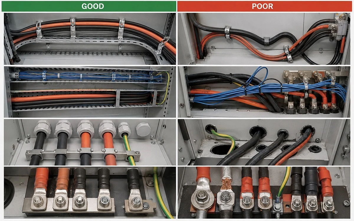
Good and poor BESS cable routing
Routing affects temperature, electromagnetic compatibility, fault exposure and maintainability. Separate power and communications as required, protect cables from sharp edges and moving parts, preserve bend radius, support cable weight, limit parallel-path imbalance, and provide clear polarity and circuit labels. In liquid-cooled equipment, prevent coolant leaks or service work from damaging electrical cables..
Routing affects temperature, electromagnetic compatibility, fault exposure and maintainability. Separate power and communications as required, protect cables from sharp edges and moving parts, preserve bend radius, support cable weight, limit parallel-path imbalance, and provide clear polarity and circuit labels. In liquid-cooled equipment, prevent coolant leaks or service work from damaging electrical cables.
Where dense routing and thermal conditions are significant, coordinate the cable design with the liquid-cooled industrial battery cabinet enclosure layout and service access.
BESS cable standards and compliance
No single global cable designation automatically covers every BESS circuit. Product standards, installation codes, equipment standards and national requirements interact. The engineer must identify the cable's permitted use, voltage, temperature, fire performance and installation method, and verify current certificates for the exact manufacturer, factory, model and size.
|
Reference area |
Examples to investigate |
Project use |
|
Cable/conductor construction |
IEC 60228; applicable IEC/EN/UL cable product standard |
Conductor class, resistance, voltage, materials and testing. |
|
Electrical installation |
IEC 60364 series or locally adopted electrical code; NEC where applicable |
Ampacity, protection, routing, grounding and installation. |
|
BESS safety |
IEC 62933-5-1/-5-2; UL 9540; NFPA 855 where adopted |
System hazards, installation and lifecycle safety context. |
|
Power conversion |
IEC 62477-1 or applicable converter standard |
PCS electrical safety and interface constraints. |
|
Transport/equipment wiring |
Project- and product-specific requirements |
Harness, enclosure, vibration, flame and environmental needs. |
Standards listed here are starting points, not a universal compliance declaration. Confirm the applicable edition and jurisdiction with the designer, certification body and authority having jurisdiction.
Procurement documentation checklist
For coordinated PV-side and battery-side routing, use the solar-plus-storage guide.
- Approved cable datasheet with conductor, insulation, sheath, voltage and temperature ratings.
- Current certificate/database record where certification is required.
- Maximum conductor resistance and applicable ampacity information.
- Outer diameter, minimum bend radius, mass and drum/reel data.
- Terminal/lug/gland compatibility schedule and approved tooling.
- Type-test, routine-test and batch inspection requirements.
- Cable marking, polarity colors, length tolerances and traceability.
- Factory, certificate holder and change-notification requirements.
- Packaging, sealing, transport and site-storage instructions.
For adjacent solar-side cabling decisions, use the existing Solar DC Cable Selection Guide 2026 while keeping PV cable and BESS cable duties technically distinct.
The downloadable SINELINK PV cable product catalog can support product discovery, but the exact BESS application and approved documentation must still be confirmed.
Send SINELINK the DC voltage range, maximum current, one-way route length, ambient temperature, installation method, cable grouping, terminal details, destination country and required standards.
Common BESS cable specification mistakes
- Using nominal battery voltage instead of maximum circuit voltage.
- Selecting cross-section from current alone without derating or voltage-drop checks.
- Ignoring fault current and DC protective-device clearing time.
- Assuming all 1000V or 1500V cables have the same permitted use.
- Specifying a cable size that the lug, contact or gland does not accept.
- Mixing copper and aluminum without compatible terminals and transition design.
- Ignoring parallel-cable length, routing and resistance balance.
- Treating a certificate PDF as proof without checking model, size, factory and current status.
Frequently asked questions
Q:What cable is used for a BESS?
The correct cable depends on the circuit. BESS projects may use flexible battery interconnect cable, higher-current DC feeder cable, AC power cable, protective-earth cable and control/communication cable, each with its own rating and approval.
Q:How do I size a BESS DC cable?
Check maximum voltage, design current, corrected ampacity, voltage drop, short-circuit withstand, installation environment and termination compatibility under the applicable code.
Q:Is 1000V cable suitable for a 1000V battery system?
Not automatically. Confirm maximum circuit voltage, rating convention, transients, conductor-to-earth requirements, temperature, installation method and equipment terminals.
Q:Can PV cable be used in a BESS?
Only when the cable's approved scope and project requirements permit that specific duty. A PV cable designation does not automatically prove suitability for internal battery wiring or high-current battery-to-PCS feeders.
Q:Copper or aluminum for BESS feeders?
Both can be used in engineered applications. Aluminum normally requires a larger cross-section and compatible lugs, oxide control, thermal-expansion consideration and installation procedures.
Q:How much voltage drop is acceptable?
The project designer sets the limit based on efficiency, PCS voltage window, route length and economics. Apply one consistent measurement boundary and operating case.
Q:Why are BESS cable terminals critical?
Many failures originate at high-resistance connections. Correct conductor/lug matching, crimp tooling, torque, sealing, support and inspection are essential.
Q:Should positive and negative DC cables have the same length?
Routes should be designed to maintain appropriate impedance and current balance, especially for parallel paths. Exact requirements depend on the architecture and manufacturer instructions.
Q:What documents should buyers request?
Request datasheets, certificates, resistance and dimension data, test reports, terminal compatibility, marking/traceability, inspection records and packing/storage instructions.
Q:Can cable sizing be completed from this guide alone?
No. This guide supports specification and procurement; final design must be completed by the responsible engineer under applicable codes and equipment instructions.
Need a cable schedule for a commercial or industrial storage project? Submit the electrical and installation inputs for a preliminary product match.
Conclusion
Reliable BESS cabling begins with the circuit and installation-not a catalogue size. Align voltage, corrected ampacity, voltage drop, fault withstand, materials, environment, terminals, routing, documentation and inspection. This approach reduces avoidable losses, overheating, installation rework and interface disputes across the storage plant.