

BESS KNOWLEDGE SERIES
How Does a Battery Energy Storage System Work?
A battery energy storage system (BESS) charges by converting electricity into DC power and storing it electrochemically in battery cells. When energy is needed, the process reverses: the battery releases DC power, the power conversion system (PCS) converts it to controlled AC power, and the energy management system (EMS) coordinates dispatch according to site or grid objectives. Throughout the process, the battery management system (BMS) monitors cell conditions and enforces safe operating limits.
That simple description hides a coordinated sequence of electrical conversion, measurement, decision-making and protection. In a commercial or industrial project, the battery does not decide independently when to charge or discharge. The BMS, PCS, EMS, meters, protection devices and site controller exchange limits and commands continuously so that the plant can deliver the required power without exceeding electrical, thermal or contractual boundaries.
For the full design, sizing, safety and procurement framework, read the complete guide to battery energy storage systems before finalizing the system specification.
On This Page
- BESS working principle in one minute
- What Happens During BESS Charging?
- What Happens During BESS Discharging?
- How the BMS, PCS and EMS Work Together
- AC-Coupled vs DC-Coupled BESS: How Operation Changes
- How BESS Operating Modes Change by Application
- BESS Efficiency, State of Charge and State of Health
- How a BESS Responds to Faults and Shuts Down Safely
- BESS Operational Due-Diligence Checklist
- Frequently asked questions
- Conclusion
BESS working principle in one minute
A BESS operates as a controlled, bidirectional energy buffer. Meters measure the site and grid; the EMS determines the desired action; the BMS confirms the battery's allowable limits; the PCS converts power in the required direction; protection systems supervise the process; and SCADA records performance and alarms.
The control loop repeats continuously. Response speed depends on the service and architecture: a demand-management controller may act before a billing threshold is exceeded, while a grid-support controller may respond rapidly to voltage or frequency conditions. The required response, accuracy and measurement boundary should be specified rather than assumed.
What Happens During BESS Charging?
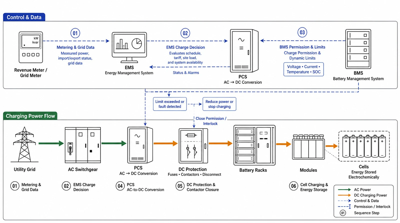
Charging begins when the EMS or plant controller requests energy absorption. The source may be the utility grid, onsite solar generation, a generator or another AC/DC source. In an AC-coupled system, the PCS converts AC electricity into DC. In a DC-coupled solar-plus-storage design, a DC converter or shared inverter architecture controls energy transfer between PV, battery and the DC bus.
The charging sequence
Charge power is not always constant. It can taper near high SOC, fall at low or high temperatures, or be limited by cell imbalance, PCS capacity, transformer loading, site import limits or available PV. Procurement models should therefore use an operating curve, not assume rated power is available at every SOC and temperature.
BESS Charging sequence
What Happens During BESS Discharging?
During discharge, the battery releases DC energy. The PCS converts it into synchronized AC power for the facility or grid. The EMS determines the dispatch level, but the BMS continuously limits the command to keep cells inside permitted voltage, current, temperature and SOC boundaries.
The discharging sequence
A BESS may have sufficient stored energy yet still be unable to deliver rated power if temperature, SOC, DC voltage, battery current, PCS rating, reactive-power requirements or protection limits reduce the available output. Power and energy guarantees must state their operating conditions.
How the BMS, PCS and EMS Work Together
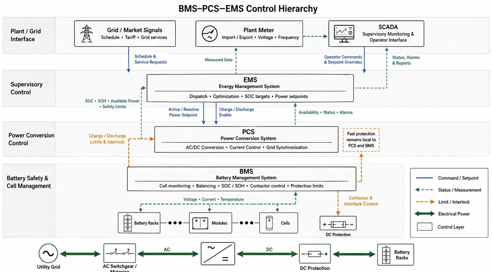
For detailed equipment scope and procurement interfaces, see battery, BMS, PCS and EMS components before finalizing the controls responsibility matrix.
|
System |
Decision or action |
Typical information exchanged |
|
BMS |
Protects and supervises the battery; estimates SOC/SOH; calculates allowable charge and discharge limits. |
Cell/rack voltage and temperature, SOC, SOH, current limits, alarms, contactor state. |
|
PCS |
Converts power and regulates the electrical interface. |
Power setpoint, DC voltage/current, AC voltage/frequency, reactive power, status and faults. |
|
EMS / plant controller |
Selects operating mode and optimizes dispatch across the site or grid objective. |
Meter data, forecasts, tariffs, reserve target, grid commands, equipment availability and constraints. |
|
SCADA / monitoring |
Visualizes, records and communicates plant status. |
Time-series data, alarms, events, user commands, reports and remote access. |
A robust controls design uses limits and permissives rather than relying on one controller to understand every internal detail. The EMS requests an operating point; the BMS declares the battery's current allowable envelope; and the PCS executes the command only while all required interlocks are true. If communications fail, each subsystem should enter a defined safe state.
Why the interface matrix matters
- Identify which device is the authoritative source for SOC, active power, reactive power and grid status.
- Define update rate, units, scaling, timestamps, quality flags and communication-loss timers.
- List every alarm, warning, trip, reset, emergency stop and maintenance override.
- Document command priority between local controls, EMS, utility/aggregator and operator SCADA.
- Test abnormal states, not only normal charge and discharge commands.
AC-Coupled vs DC-Coupled BESS: How Operation Changes
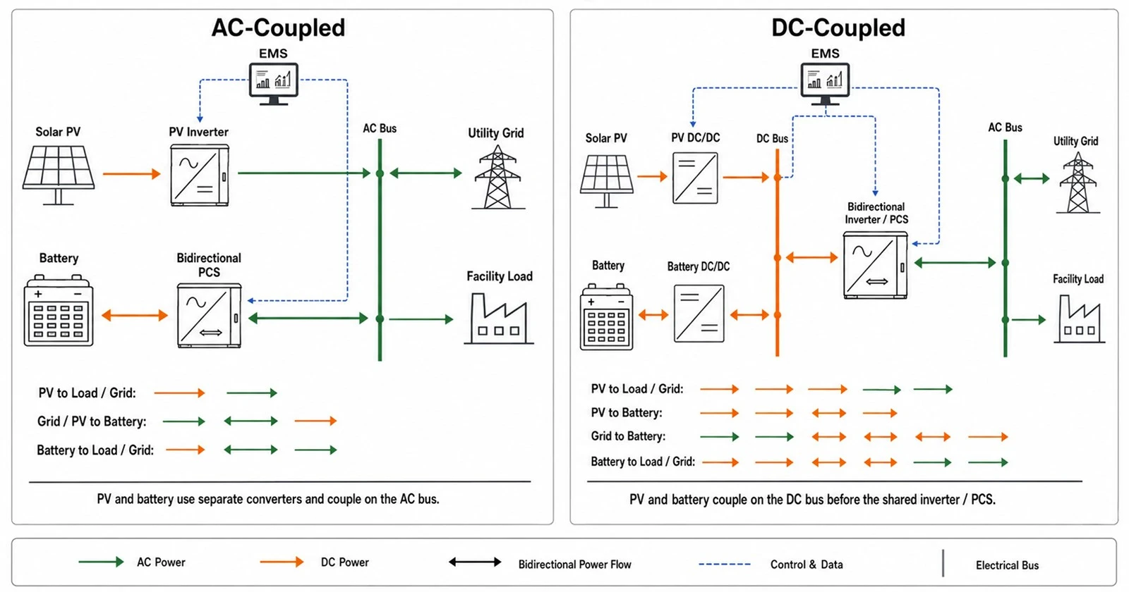
Apply the coupling comparison in the solar-plus-storage guide.
|
Factor |
AC-coupled |
DC-coupled |
|
Power path |
Battery uses a dedicated PCS and connects on the AC bus. |
PV and battery share a DC-side architecture before grid conversion. |
|
Retrofit fit |
Often straightforward where PV or facility AC infrastructure already exists. |
Usually requires closer integration with PV inverter/DC architecture. |
|
Independent control |
PV and BESS can often operate as separate AC assets. |
PV and storage controls are more tightly coordinated. |
|
Stored-solar conversion |
PV AC may be converted back to DC for storage, then back to AC. |
Can reduce conversion stages when storing PV directly on the DC side. |
|
Design checks |
AC switchgear, transformer, interconnection capacity and protection. |
DC voltage windows, current paths, converter limits, protection and fault isolation. |
|
Best choice |
Depends on retrofit constraints, operating flexibility and grid connection. |
Depends on curtailment/clipping capture, new-build design and integrated controls. |
AC coupling is commonly attractive for retrofits and independent asset control. DC coupling can be attractive for new solar-plus-storage plants where direct capture of PV energy or clipping is important. Compare energy paths, interconnection constraints, operating modes, maintainability and lifecycle economics for the specific project.
How BESS Operating Modes Change by Application
Threshold dispatch and recharge behavior are detailed in the BESS peak shaving guide.
Facility-level priorities are developed further in the C&I BESS practical guide.
|
Application |
Trigger |
Control objective |
Main operational constraint |
|
Peak shaving |
Facility demand approaches a threshold. |
Discharge before and during the peak; recharge without creating another peak. |
Forecast accuracy, available SOC and peak duration. |
|
Time-of-use shifting |
Scheduled tariff periods or optimized price signal. |
Charge low, discharge high. |
Price spread after losses and degradation. |
|
Solar self-consumption |
PV exceeds onsite demand or export limit. |
Absorb surplus PV and discharge later. |
PV forecast, export limit and battery headroom. |
|
Backup / islanding |
Grid outage or planned transfer. |
Maintain critical loads and coordinate islanded sources. |
Grid-forming capability, transfer logic, load steps and reserve. |
|
Grid support |
Frequency, voltage or external dispatch signal. |
Provide accurate active/reactive response. |
Interconnection approval, telemetry, availability and SOC management. |
For demand-charge control applications, review the peak shaving battery system and validate the configuration against the facility load profile.
Projects requiring active interaction with the utility can review SINELINK's grid-connected battery storage solution as a starting point for technical discussion.
BESS Efficiency, State of Charge and State of Health
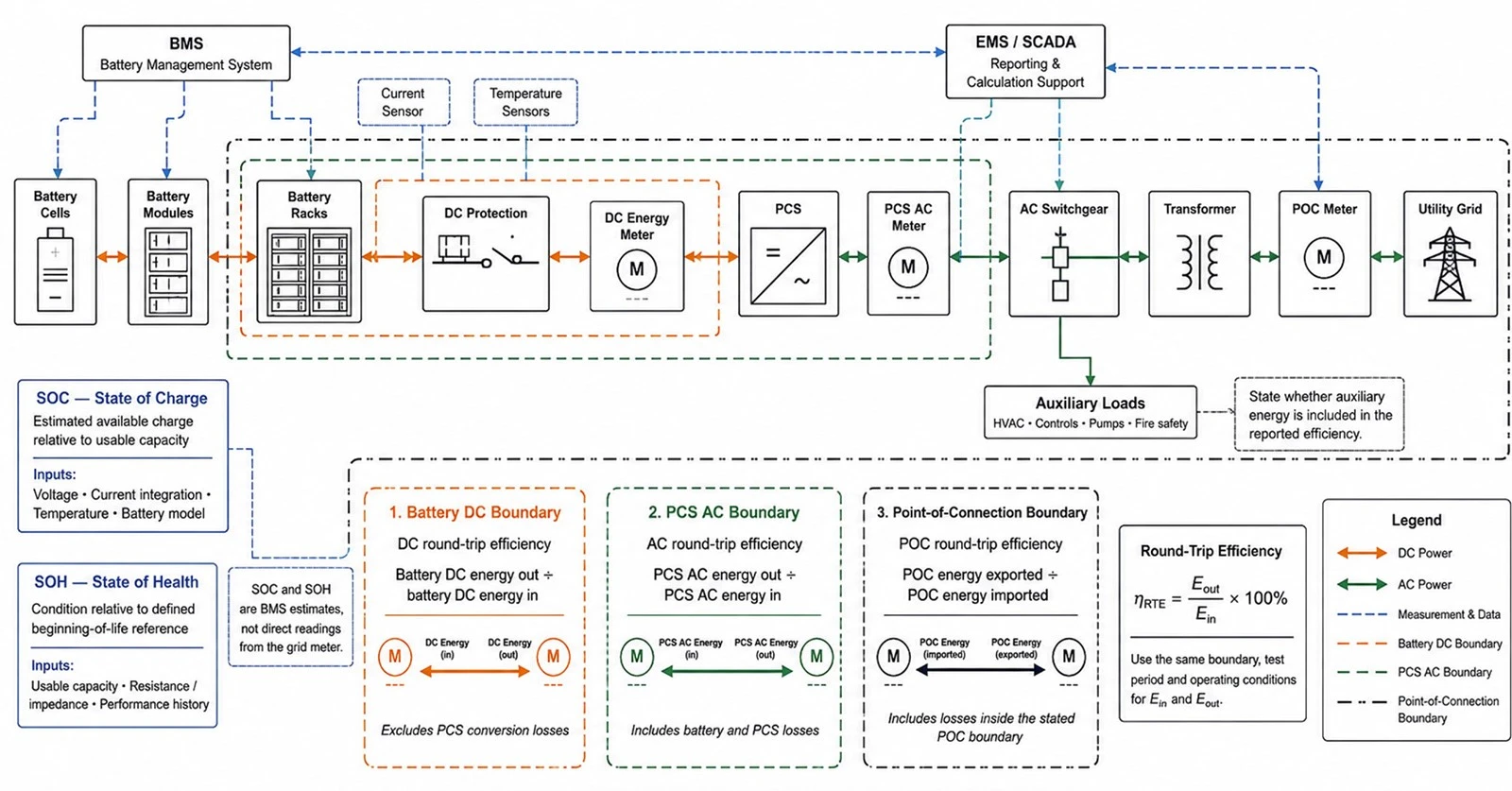
Apply these operating concepts using the BESS sizing guide before selecting a battery or PCS rating.
State of charge (SOC)
SOC estimates the remaining charge relative to a defined usable or nominal reference. It is not measured directly like voltage; the BMS estimates it from current integration, voltage behavior, temperature and cell models. Accuracy can drift, so the control strategy may include recalibration conditions.
State of health (SOH)
SOH describes battery condition relative to an agreed reference, often using available capacity, resistance or power capability. Because suppliers may calculate SOH differently, contracts should rely on a defined capacity or performance test rather than an unexplained dashboard percentage.
Round-trip efficiency
Round-trip efficiency equals energy delivered divided by energy used to charge over a defined cycle and measurement boundary. A battery-only DC value is not comparable with an AC system value that includes PCS, transformer and auxiliary loads. Efficiency also changes with power, temperature and standby duration.
Degradation
Calendar aging occurs with time; cycle aging results from use. Both are influenced by temperature, SOC, depth of discharge, rate and cell design. The EMS can trade short-term revenue against long-term degradation by limiting SOC, power or throughput. Project models should use the warranted duty cycle and a transparent augmentation assumption.
How a BESS Responds to Faults and Shuts Down Safely
Abnormal states and lifecycle controls are covered in the BESS safety guide.
Cable ratings and termination interfaces are part of the protection path; consult the BESS cable selection guide when defining current, fault and installation limits.
A BESS should not depend on software dispatch alone for protection. Electrical and safety layers detect abnormal current, voltage, insulation, temperature, smoke, gas or equipment state and isolate the affected level. The exact response depends on the architecture and hazard analysis, but a typical sequence is to reduce power, open contactors or breakers, isolate the fault, maintain required detection/ventilation functions, issue alarms and prevent unauthorized restart.
- Cell/module level: voltage and temperature monitoring, balancing and protective limits.
- Rack level: contactors, fuses, current sensing, insulation monitoring and local control.
- PCS/AC level: overcurrent, grid abnormality, anti-islanding and breaker protection.
- System level: emergency stop, fire/gas detection, ventilation logic, access control and SCADA alarms.
- Operational level: lockout/tagout, emergency plan, damaged-equipment controls and controlled return to service.
UL 9540A is a thermal-runaway fire-propagation test method; it is not a universal statement that every installation is safe. Project teams must confirm the tested configuration, equipment certification, adopted codes, installation conditions and AHJ requirements.
BESS Operational Due-Diligence Checklist
- The complete power-flow diagram and metering boundary for every guaranteed value.
- Battery voltage/current limits against PCS operating range across SOC and temperature.
- Normal, standby, black-start, islanding, recovery and emergency operating sequences as applicable.
- BMS–PCS–EMS signal list, command priority and communication-loss behavior.
- Auxiliary consumption in charging, discharging, standby and extreme ambient conditions.
- Capacity, efficiency and response tests in FAT/SAT and the final acceptance criteria.
- Alarm ownership, remote-access controls, software update responsibilities and event-data retention.
- Warranty assumptions for temperature, SOC window, throughput, C-rate and availability.
Need to map BESS operating modes to your load profile or grid requirements? Send SINELINK your application, target kW/kWh, grid voltage, site conditions and preferred system architecture.
For mainstream high-voltage C&I integration, review the 1000V high-voltage battery system platform and confirm its operating window against the selected PCS.
Sites with high ambient temperatures or dense packaging requirements can evaluate a liquid-cooled industrial battery cabinet while confirming cooling redundancy and service needs.
Frequently asked questions
Does a BESS store AC or DC power?
Battery cells store energy electrochemically and deliver DC electrical power. The PCS converts between battery DC and the AC system used by most facilities and grids.
Can a BESS charge and discharge at the same time?
A single battery string does not normally charge and discharge simultaneously. At plant level, different strings or subsystems may operate differently, but controls must prevent unintended circulating power and respect the architecture.
What controls when a BESS charges or discharges?
The EMS or plant controller applies schedules, tariffs, forecasts, site limits or grid commands. The BMS and PCS then limit or reject commands that fall outside safe equipment conditions.
What happens when a BESS reaches 100% SOC?
The BMS reduces or stops allowable charge as cells approach their upper limits. Many projects operate below absolute maximum SOC to preserve headroom, life or safety margin.
Can a grid-tied BESS operate during a power outage?
Only if the PCS, protection and controls are designed for islanding or grid-forming operation and the site has an approved transfer, grounding and load-management scheme.
Why does available BESS power change?
Available power can be limited by SOC, cell temperature, DC voltage, allowable current, PCS temperature, reactive-power duty, auxiliaries, faults or grid conditions.
What is the difference between EMS and SCADA?
The EMS makes or coordinates dispatch decisions. SCADA primarily provides supervisory control, visualization, alarms and historical data, although product boundaries can overlap.
How is BESS efficiency measured?
Measure energy entering and leaving across the same defined boundary and cycle. State whether the figure includes PCS, transformer, HVAC and other auxiliaries.
What happens if BMS communication is lost?
The defined safe behavior may include holding a conservative limit, ramping to zero or tripping after a timeout. The exact sequence should be specified and tested.
How does a BESS support peak shaving?
The controller monitors site import and discharges before demand exceeds a target. It also schedules recharge to preserve SOC without producing a new peak.
Planning a commercial or industrial battery storage project? Share your load profile, use case, target duration, grid connection and compliance market.
Conclusion
A BESS works through continuous coordination rather than a simple battery on/off command. The EMS defines the objective, the BMS protects the battery, the PCS controls power conversion, and protection and monitoring systems verify every operating state. Project teams that define these interfaces, limits and measurement boundaries early are better positioned to obtain predictable performance, safe operation and enforceable warranties.