

Battery energy storage system engineering reference
BESS COMPONENTS
BESS Components Explained: Battery, BMS, PCS, EMS and Balance of System
TECHNICAL ARCHITECTURE • INTERFACES • PROCUREMENT
TECHNICAL ANSWER
The main components of a battery energy storage system are battery cells assembled into modules and racks, a battery management system (BMS), a power conversion system (PCS), an energy management system (EMS), thermal management, electrical protection, fire and gas safety equipment, metering, communications, and balance-of-system equipment such as transformers and switchgear. These components must be engineered as one coordinated plant; a compatible parts list alone does not guarantee safe or reliable operation.
For procurement teams, the most important question is not simply whether each component is present. It is whether ratings, interfaces, control authority, test evidence and warranties remain consistent across the complete operating envelope. A weakness at one interface-battery voltage versus PCS range, BMS limits versus EMS commands, or enclosure cooling versus site temperature-can restrict the entire system.
Start with the complete guide to battery energy storage systems for the parent framework covering design, applications, safety and procurement.
If you first need the operating sequence, read how a battery energy storage system works to see how the BMS, PCS and EMS coordinate during charging and discharging.
ON THIS PAGE
- BESS component architecture at a glance
- 1. Battery cells, modules and racks
- 2. Battery management system (BMS)
- 3. Power conversion system (PCS)
- 4. Energy management system (EMS) and plant controller
- 5. Thermal management
- 6. Electrical protection and DC/AC distribution
- 7. Fire, gas and emergency systems
- 8. Transformer, switchgear and grid interface
- 9. SCADA, communications and cybersecurity
- 10. Auxiliary systems and enclosure
- How to verify component compatibility
- BESS component procurement checklist
- Frequently asked questions
- Conclusion
BESS component architecture at a glance
See how these components are packaged for sites in theC&I BESS practical guide.
ENGINEERING SUMMARY
Battery hardware stores energy; the BMS protects and supervises it; the PCS converts power; the EMS selects operating objectives; protection and safety systems manage abnormal conditions; thermal systems maintain equipment conditions; and transformers, switchgear, metering and communications connect the BESS to the site and grid.
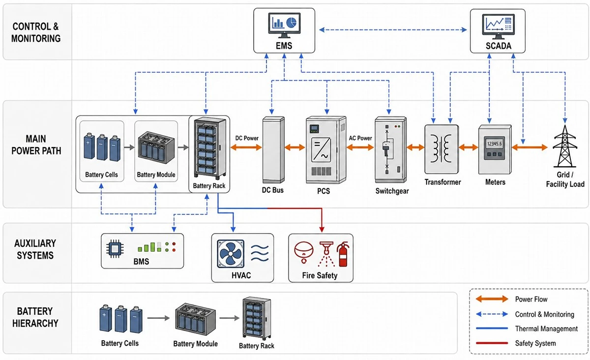
|
Layer |
Components |
Primary responsibility |
|
Energy storage |
Cells, modules, racks, DC bus |
Store energy and provide the required DC voltage, current and capacity. |
|
Battery control |
Cell, module, rack and master BMS |
Monitor conditions, estimate SOC/SOH, balance cells and enforce limits. |
|
Power conversion |
PCS/inverter, filters, DC and AC switching |
Convert power bidirectionally and regulate the grid/load interface. |
|
Plant control |
EMS, plant controller, site controller |
Schedule and optimize dispatch while coordinating constraints. |
|
Safety and environment |
Cooling, heating, detection, ventilation, suppression/mitigation |
Maintain conditions and reduce electrical, thermal, fire and gas risks. |
|
Grid/site interface |
Transformer, switchgear, relays, meters, SCADA, communications |
Connect, protect, measure and communicate with the facility or utility. |
1. Battery cells, modules and racks
Cells are the smallest electrochemical units. Manufacturers combine cells into modules, modules into packs or trays, and those assemblies into racks or cabinets. Series connections raise voltage; parallel connections increase current and energy capability. The mechanical and electrical arrangement affects fault current, serviceability, thermal behavior and propagation risk.
What to specify
- Chemistry, cell format, supplier traceability and manufacturing quality controls.
- Nominal and usable energy at defined SOC, temperature, power and beginning/end-of-life conditions.
- DC voltage window, maximum continuous and short-duration current, C-rate and derating curves.
- Cycle and calendar-aging assumptions, throughput limits and augmentation strategy.
- Module/rack isolation, fusing, contactors, service clearances and replacement method.
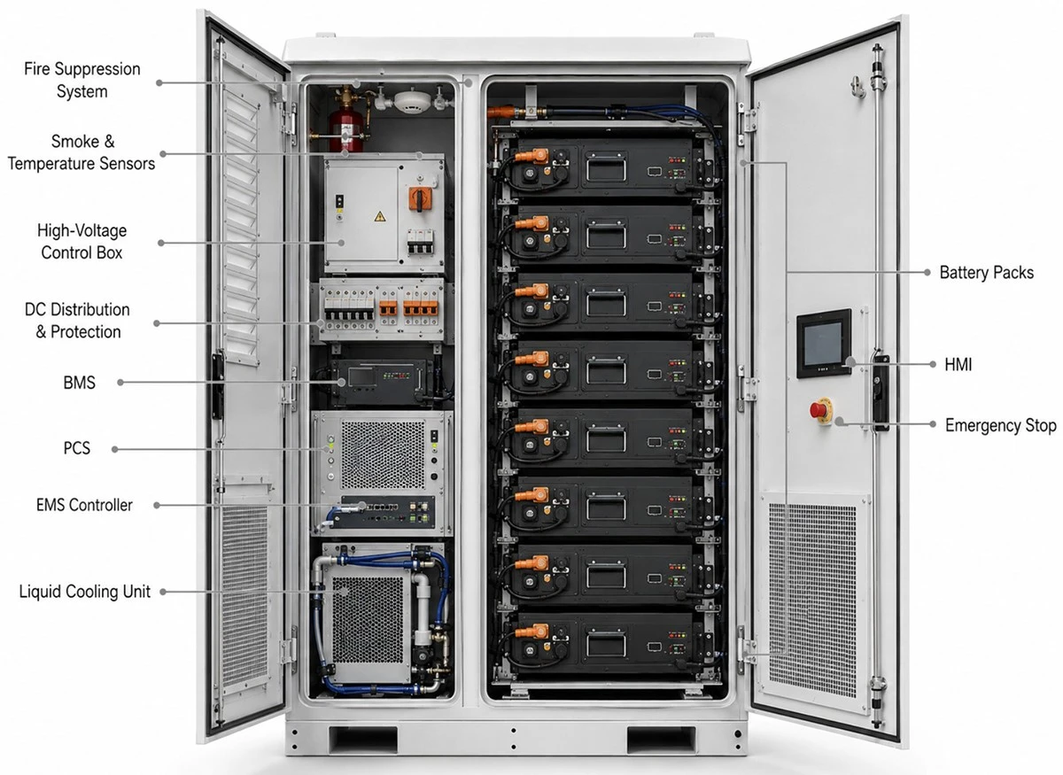
For a modular C&I voltage platform, review the 1000V high-voltage battery system and verify its full DC operating range against the selected PCS.
For larger 1500V-class architectures, compare the 1331V high-voltage battery platform with project current, protection, insulation and service requirements.
2. Battery management system (BMS)
The BMS measures cell and module voltage, temperature and current; estimates state of charge and state of health; manages balancing; calculates allowable charge and discharge limits; controls contactors; records events; and communicates battery status to the PCS and EMS. A BMS is a layered system rather than one sensor board, often including module, rack and master controllers.
TECHNICAL ANSWER
The BMS protects the battery and publishes its allowable operating envelope. It does not normally optimize electricity cost or market dispatch; that is the EMS role. The PCS should respect BMS current and power limits even when the EMS requests a higher setpoint.
BMS interface questions
- Which device is the authoritative source for SOC, SOH, allowable power and fault state?
- How often are limits updated, and what happens when communications are delayed or lost?
- Which alarms cause derating, controlled shutdown or immediate isolation?
- How are event records, firmware versions, remote access and cybersecurity managed?
- Can the BMS support mixed-age racks after augmentation or replacement?
3. Power conversion system (PCS)
PV and storage equipment interfaces are mapped in the solar-plus-storage guide.
The PCS is the bidirectional electrical bridge between the battery DC bus and the AC system. During charging it converts AC to DC; during discharge it converts DC to AC. Depending on the design, it also controls reactive power, power factor, harmonics, ramp rate, voltage/frequency response, anti-islanding and fault ride-through.
PCS selection checks
- DC voltage range across minimum/maximum SOC, temperature and degradation.
- Continuous and overload power at site ambient temperature and altitude.
- Efficiency curve-not only peak efficiency-and standby consumption.
- Reactive-power capability and whether it reduces available active power.
- Grid-code functions, transformer compatibility, harmonics and short-circuit contribution.
- Grid-following versus grid-forming capability for backup or microgrid use.
For projects that actively exchange power with the utility, review grid-connected battery storage and confirm all grid functions through the applicable interconnection study and field tests.
4. Energy management system (EMS) and plant controller
A real threshold-dispatch example is provided in the BESS peak shaving guide.
The EMS converts business or grid objectives into dispatch commands. It can monitor load and generation, forecast peaks, manage SOC reserve, respond to tariffs or market signals, coordinate generators and PV, and send setpoints to the PCS. In larger projects, a plant controller may handle fast point-of-connection requirements while the EMS performs slower optimization.
TECHNICAL ANSWER
The EMS decides when and why the BESS should operate; the PCS determines how electrical power is converted; the BMS determines how much battery power is currently permissible. Clear ownership of setpoints, limits and fallback behavior is essential.
EMS procurement requirements
- Operating modes, priority rules and conflict resolution for stacked use cases.
- Metering sources, forecast inputs and control response time.
- Protocols, API availability, historian, time synchronization and data ownership.
- Local operation during cloud or WAN loss and defined safe fallback states.
- User roles, authentication, audit logs, patching and remote-support obligations.
5. Thermal management
Thermal management maintains cells and power electronics within specified temperatures and limits temperature variation. Air-cooled systems may offer simpler service, while liquid cooling can support tighter temperature control and higher packaging density. Selection should consider ambient design, humidity, dust, corrosion, redundancy, auxiliary energy, noise, leak detection and maintainability-not cooling method alone.
For demanding climates or high-density layouts, evaluate a liquid-cooled industrial battery cabinet while checking cooling-loop redundancy, parasitic load and service capability.
6. Electrical protection and DC/AC distribution
For conductor sizing and procurement inputs, continue to the BESS cable selection guide covering voltage, current, voltage drop, fault withstand and installation conditions.
Protection equipment detects and isolates faults. The architecture may include cell/rack fuses, contactors, DC disconnects, insulation monitoring, surge protection, AC breakers, protection relays, grounding systems and emergency-stop circuits. Coordination studies must consider battery and PCS fault behavior, transformer contribution and the site network.
- Define isolation boundaries for module, rack, PCS, transformer and point of connection.
- Coordinate trip thresholds and timing so the smallest practical faulted section is isolated.
- Evaluate shock, arc-flash, stored-energy and lockout/tagout requirements.
- Confirm DC cable and busbar voltage, current, temperature and short-circuit ratings.
7. Fire, gas and emergency systems
The complete safety evidence chain is covered in the BESS safety guide.
Safety architecture can include cell analytics, smoke/heat/off-gas detection, ventilation, pressure relief, separation, fire suppression or other mitigation, emergency power and responder interfaces. Requirements depend on chemistry, enclosure, energy capacity, test evidence, applicable codes and the authority having jurisdiction. A suppression device or certificate is not a complete safety case.
ENGINEERING SUMMARY
UL 9540 addresses energy storage systems and equipment, while UL 9540A is a test method for thermal-runaway fire propagation behavior. Procurement teams should review the exact models, configuration, test level and installation conditions-not only a certificate name.
8. Transformer, switchgear and grid interface
The transformer matches the PCS voltage to the facility or utility network. Switchgear, protection relays and revenue or operational meters establish the connection boundary. Design checks include voltage ratio, vector group, impedance, losses, harmonics, grounding, short-circuit duty, protection coordination, auxiliary supply and utility requirements.
For megawatt-scale industrial sites, a medium-voltage industrial ESS may simplify the grid interface, subject to detailed protection and utility review.
9. SCADA, communications and cybersecurity
SCADA provides visibility, alarms, trends and supervisory commands. Communications connect the BMS, PCS, EMS, meters, relays and external utility or aggregator. Project teams should define protocol versions, signal mapping, update rates, time synchronization, network segmentation, remote access, credential ownership, logging and software lifecycle responsibilities.
10. Auxiliary systems and enclosure
Auxiliaries include HVAC pumps or fans, heaters, controls power, lighting, detection, ventilation, communication equipment and sometimes backup power. Their consumption reduces net delivered energy and should be measured or modeled. The enclosure must address environmental rating, corrosion, drainage, condensation, noise, transport, lifting, access, egress and maintenance clearances.
How to verify component compatibility
After checking interfaces, use the BESS sizing guide to align battery energy, current limits, PCS power and end-of-life performance.
|
Interface |
Compatibility evidence |
|
Battery ↔ PCS |
Voltage/current envelope, pre-charge sequence, contactor logic, fault response and tested communications. |
|
BMS ↔ EMS |
SOC/SOH source, charge/discharge limits, alarms, mode control and communication-loss behavior. |
|
PCS ↔ transformer/grid |
Voltage, power, reactive capability, harmonics, grounding, protection and grid-code tests. |
|
Cooling ↔ battery/enclosure |
Heat-load calculation, ambient derating, redundancy, sensors, alarms and auxiliary energy. |
|
Safety system ↔ installation |
Hazard analysis, representative test evidence, detection/ventilation logic and emergency plan. |
|
SCADA ↔ all devices |
Approved signal list, timestamps, protocols, cybersecurity and FAT/SAT scripts. |
BESS component procurement checklist
- Define the complete system boundary and named supplier for every subsystem.
- Request controlled datasheets, certificates and complete test reports tied to exact models.
- Require a battery–PCS–EMS interface matrix and approved firmware versions.
- Specify power, usable energy, efficiency and auxiliaries at a common measurement boundary.
- Align component and system warranties with the project duty cycle and remedies.
- Include FAT, site acceptance, capacity, operating-mode and fault-response tests.
- Confirm spares, replacement compatibility, software support and service response.
- Plan augmentation, damaged-equipment handling and end-of-life responsibilities.
Send SINELINK your required kW/kWh, DC/AC voltage, use case, ambient conditions, grid requirements and preferred architecture.
FAQ
Q:What are the four core BESS components?
The four most commonly referenced core components are the battery, BMS, PCS and EMS. A deployable system also requires thermal management, protection, safety equipment, metering, communications and grid/site interface equipment.
Q:Is the inverter the same as the PCS?
In BESS projects, PCS often refers to the bidirectional inverter and associated conversion/control functions. Supplier scope varies, so confirm whether DC/AC switching, filters and controls are included.
Q:What is the difference between BMS and EMS?
The BMS supervises and protects the battery. The EMS optimizes when and why the plant operates while respecting BMS and PCS constraints.
Q:Does every BESS need a transformer?
No. A transformer is needed when PCS output voltage and the connection voltage differ or isolation/grounding design requires it. Some low-voltage systems connect without a dedicated transformer.
Q:Which component determines BESS power?
Available power is constrained by the lowest applicable limit among battery current/voltage, PCS rating, temperature, SOC, reactive duty, transformer/switchgear and grid conditions.
Q:Which component determines BESS capacity?
Battery nameplate energy is the starting point, but usable delivered energy also depends on SOC window, temperature, degradation, conversion losses and auxiliary consumption.
Q:Can BMS, PCS and EMS come from different suppliers?
Yes, but interface ownership, protocol compatibility, firmware control, testing and warranty responsibility must be explicit.
Q:What documents prove component compatibility?
Use approved interface specifications, operating envelopes, communication matrices, single-line diagrams, certificates/test reports, FAT/SAT results and an integrated performance guarantee.
Planning a commercial or industrial BESS? Request a component-level configuration review and documentation checklist.
Conclusion
BESS performance is determined by the interfaces between components as much as by the components themselves. A sound project aligns the battery operating envelope, BMS limits, PCS capabilities, EMS objectives, thermal design, protection, safety evidence and grid interface under one testable specification and lifecycle responsibility model.