

BESS CAPACITY PLANNING / ENGINEERING MODEL
How to Size a Battery Energy Storage System: Power, Energy, Duration and Degradation
Translate operating requirements into defensible power, usable energy and end-of-life guarantees.
DIRECT ANSWER
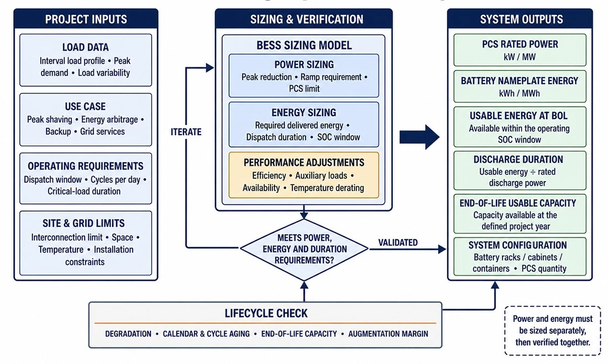
Size a BESS by defining the use case and analyzing time-series load or generation data. Determine required power in kW or MW from the maximum controlled demand, critical load or grid-service obligation. Determine required usable energy in kWh or MWh from the dispatch duration and energy profile. Then adjust for SOC limits, conversion losses, auxiliary consumption, temperature, degradation, availability, recharge constraints and end-of-life performance. Validate the result with a dispatch simulation and contractual performance schedule.
POWER
kW / MW requirement
ENERGY
Usable kWh / MWh
DURATION
Energy ÷ power
GUARANTEE
End-of-life output
A BESS should not be sized from one monthly electricity bill, a generic "two-hour" label or a supplier's nameplate capacity alone. The correct rating depends on when power is needed, how long it must be sustained, how often the battery cycles, what reserve must remain, and which measurement boundary is guaranteed.
For the broader engineering and procurement framework, read the complete battery energy storage system guide before approving a capacity recommendation.
Review how a battery energy storage system works to understand how SOC, BMS limits and PCS operating conditions affect available output.
On This Page
- Power, energy and duration: the essential difference
- Step 1: define the use case and operating rules
- Step 2: collect and validate time-series data
- Step 3: calculate the required power
- Step 4: calculate usable energy
- Step 5: model SOC window and reserve
- Step 6: apply efficiency and auxiliary consumption
- Step 7: account for degradation and augmentation
- Step 8: include temperature, availability and derating
- Step 9: model recharge and stacked services
- Step 10: convert the model into guarantees
- Illustrative sizing example: peak shaving
- BESS sizing procurement checklist
- Frequently asked questions
- Conclusion
Power, energy and duration: the essential difference
QUICK ANSWER
Power (kW or MW) is the rate at which a BESS charges or discharges. Energy (kWh or MWh) is the amount it can deliver or absorb. Duration in hours equals usable energy divided by discharge power at the stated operating conditions.
|
Quantity |
Meaning |
Example question |
|
Power |
Instantaneous or sustained charge/discharge rate. |
Can the BESS reduce a 1.8 MW site peak to a 1.2 MW target? |
|
Energy |
Total usable electricity over the dispatch window. |
Can it supply the required load throughout the peak period? |
|
Duration |
Usable energy ÷ discharge power. |
How long can rated power be maintained? |
|
C-rate |
Power relative to battery capacity. |
Does the cell/rack support the required power without excessive aging? |
A nominal 1 MW / 2 MWh system is described as two-hour storage at 1 MW, but actual delivered duration may be lower if the 2 MWh is nameplate energy and the project applies SOC limits, losses, auxiliaries or degradation. Always state whether energy is nameplate DC, usable DC, PCS AC or point-of-connection AC.
Step 1: define the use case and operating rules
Facility use cases are compared in the C&I BESS practical guide.
Start with a written operating philosophy. Each use case produces a different load shape, response requirement and reserve strategy. If the project stacks revenues, define which service has priority when requirements conflict.
|
Use case |
Power driver |
Energy driver |
|
Peak shaving |
Difference between uncontrolled demand and target import. |
Area above the target across the peak window. |
|
Time-of-use shifting |
Desired discharge rate or site/import limit. |
Energy moved between price periods after losses. |
|
Solar self-consumption |
Surplus PV, export limit or curtailment level. |
Surplus production available and later load. |
|
Backup |
Coincident critical load, motor starting and load steps. |
Required autonomy plus restart and reserve strategy. |
|
Grid services |
Contracted response capacity and accuracy. |
SOC needed to sustain or balance the service. |
For demand-management applications, examine the peak shaving battery system only after validating the facility interval-load profile and tariff rules.
Step 2: collect and validate time-series data
- Interval facility load-preferably a representative year at a resolution suitable for the use case.
- PV or other generation profile, curtailment and export constraints.
- Tariff intervals, demand-charge calculation and ratchet rules.
- Critical-load list, starting currents and required autonomy.
- Grid-service signal, response time, telemetry and availability rules.
- Planned load growth, production changes and future PV/EV additions.
- Data gaps, outliers, daylight-saving/time-zone issues and meter boundary.
Data quality is part of sizing. A missing peak, averaged 15-minute record or meter located upstream of an unmodeled load can change the recommendation. Document cleaning rules and retain the original dataset for audit.
Step 3: calculate the required power
For peak shaving, required discharge power is approximately the load above the target import limit, but the final value must include control margin, response delay and forecast error. For backup, use coincident critical loads and transient behavior rather than the sum of every nameplate. For grid services, use the contracted capacity and account for simultaneous reactive-power requirements that may consume PCS apparent-power capability.
KEY TAKEAWAY
The PCS rating does not always equal available active power. High ambient temperature, DC voltage, battery current limits, reactive-power duty, grid voltage and overload duration can reduce the deliverable kW.
Use BESS components explained to align the battery current envelope, PCS rating and EMS dispatch assumptions.
Step 4: calculate usable energy
For a constant-power obligation, preliminary usable energy equals required discharge power multiplied by duration. For variable loads, integrate the required power over time. Then add the energy needed to cover conversion losses and auxiliary loads according to the defined measurement boundary.
|
Sizing layer |
Conceptual calculation |
|
Required AC energy |
Integral of required delivered power over the dispatch window. |
|
PCS input energy |
Required AC energy ÷ discharge-conversion efficiency. |
|
Battery usable energy |
PCS input energy + battery-side/auxiliary allowances within the defined boundary. |
|
Installed beginning-of-life energy |
Usable requirement adjusted for SOC window, temperature and initial margin. |
|
Installed end-of-life basis |
Beginning-of-life capacity or planned augmentation adjusted for degradation guarantee. |
Do not combine every uncertainty into one unexplained margin. Show SOC fraction, efficiency, auxiliaries, temperature, degradation and availability separately so the owner can review and negotiate each assumption.
Step 5: model SOC window and reserve

Nameplate, Usable and Reserved BESS Energy Capacity
The EMS may prevent operation at absolute minimum and maximum SOC to protect the battery, maintain calibration margin or preserve backup reserve. A 10%–90% operating window exposes 80% of the relevant reference capacity before other limitations. If 20% SOC must remain for backup, daily economic dispatch has less available energy.
Step 6: apply efficiency and auxiliary consumption
Round-trip efficiency is useful for economic modeling but can hide the separate charge and discharge losses needed for capacity calculations. Obtain efficiency curves across power and voltage, not only a peak value. Define whether HVAC, pumps, heaters, controls, transformer and standby consumption are included.
- Charge efficiency and discharge efficiency by operating point.
- Transformer and cable losses at the specified boundary.
- Cooling/heating energy at seasonal ambient conditions.
- Standby and control power over long dwell periods.
- Recovery energy required after a dispatch event.
Long DC routes can affect loss assumptions; use the BESS cable selection guide to align conductor loss, voltage drop and operating temperature with the model.
Step 7: account for degradation and augmentation
Battery capacity and power capability change with calendar time and cycling. Model calendar and cycle aging using the intended temperature, average SOC, depth of discharge, C-rate and annual throughput. Supplier warranties may limit cycles, energy throughput, operating temperature or SOC window; the financial dispatch must respect those conditions.
|
Strategy |
Benefit |
Trade-off |
|
Beginning-of-life oversizing |
Simple initial design; no planned later construction. |
Higher upfront cost and underused early capacity. |
|
Planned augmentation |
Adds capacity when degradation occurs. |
Future equipment compatibility, outage, construction and price risk. |
|
Operational derating |
Protects life by limiting SOC, power or throughput. |
May reduce revenue or service capacity. |
|
Warranty-aligned dispatch |
Keeps operation within contractual limits. |
Requires EMS controls and auditable data. |
QUICK ANSWER
End-of-life sizing means the BESS must still meet the required guaranteed power and usable energy at a defined future year, operating profile and test condition. Meet this through initial oversizing, augmentation, or a combination-and state the plan contractually.
Step 8: include temperature, availability and derating
Cold conditions may restrict charge power; high temperatures may reduce PCS or battery power and increase auxiliary demand. Altitude can affect cooling and insulation. Availability modeling should separate scheduled maintenance, forced outages, partial-power operation, grid outages and external curtailment. Define whether partial capability counts as available.
Step 9: model recharge and stacked services
PV surplus, export and reserve interactions are developed in the solar-plus-storage guide.
A discharge event is only half the cycle. Confirm when sufficient energy and grid/PV capacity are available for recharge, whether charging creates a new demand peak, and whether the system can restore reserve before the next event. For stacked services, simulate priority, SOC reservation and simultaneous power limits rather than adding independent revenue estimates.
Projects with active utility dispatch can compare assumptions against grid-connected battery storage while treating interconnection approval and market qualification separately.
Step 10: convert the model into guarantees
- Rated charge/discharge power, duration and overload at stated voltage, temperature and reactive duty.
- Usable energy at a defined AC/DC measurement boundary and SOC window.
- Beginning-of-life and end-of-life capacity test methods.
- Charge, discharge and round-trip efficiency boundaries.
- Auxiliary consumption in operation and standby.
- Availability definition, exclusions, calculation period and remedy.
- Degradation curve, throughput/cycle/temperature assumptions and augmentation obligations.
- Meter accuracy, data retention, test tolerance and correction method.
Illustrative sizing example: peak shaving
For a full threshold and rebound analysis, continue to the BESS peak shaving guide.
Assume a factory wants to cap grid import at 1,200 kW. Interval data shows a 1,650 kW maximum and an irregular peak lasting about 90 minutes. The power requirement is not automatically 450 kW for 1.5 hours: the engineer must integrate the area above 1,200 kW, test forecast/control delay, confirm recharge without rebound, and simulate multiple peaks.
|
Input |
Illustrative value |
Important limitation |
|
Target import |
1,200 kW |
Must match tariff measurement and control meter. |
|
Maximum observed load |
1,650 kW |
One historical maximum is not a complete design basis. |
|
Preliminary maximum discharge |
450 kW plus justified control margin |
Subject to PCS/battery derating. |
|
Energy above target |
Calculated from interval profile |
Not simply maximum power × full peak window. |
|
Reserve and losses |
Added as separate model factors |
Must use defined conditions and boundaries. |
|
End-of-life requirement |
Same service in the specified warranty year |
Requires degradation/augmentation treatment. |
This example explains the method but is not a project design. Final sizing requires validated interval data, site studies, applicable codes and supplier performance curves.
BESS sizing procurement checklist
- Use case, dispatch priorities and operating modes approved.
- Metered load/generation data validated and archived.
- Power and energy measurement boundaries defined.
- SOC reserve, temperature and derating assumptions documented.
- Efficiency curves and auxiliary loads included.
- Degradation, throughput and augmentation plan aligned with warranty.
- Recharge windows and stacked-service conflicts simulated.
- Sensitivity cases completed for load growth, weather and forecast error.
- Guaranteed-performance schedule included in the tender and contract.

Request a Preliminary BESS Sizing Review
Send SINELINK the interval load or generation profile, target service, grid voltage, required duration, site conditions and compliance market.
Frequently asked questions
How many kWh of battery storage do I need?
Calculate the energy required over the actual dispatch profile, then adjust for SOC limits, losses, auxiliaries, temperature and degradation. A load profile and use case are required.
What is the difference between kW and kWh?
kW is power; kWh is energy. A system with 500 kW usable power and 1,000 kWh usable energy has a nominal two-hour duration at 500 kW.
How do I size a BESS for peak shaving?
Choose a target import threshold, calculate power and energy above that line using interval data, then simulate SOC, forecast error, recharge and degradation.
How do I size a BESS for backup?
Model coincident critical loads, starting currents, islanding/transfer behavior and autonomy, then include SOC reserve, conversion losses, auxiliaries and end-of-life capacity.
Should I size from nameplate or usable energy?
Use guaranteed usable energy at the project measurement boundary and operating conditions. Nameplate energy alone is insufficient.
What is a two-hour BESS?
It can nominally deliver its stated power for two hours using the stated usable energy. Confirm SOC, losses, temperature and degradation conditions.
How much oversizing is required for degradation?
There is no universal percentage. Use the warranted aging model for the intended temperature, SOC, C-rate and throughput, or plan augmentation.
Does round-trip efficiency affect sizing?
Yes, but charge and discharge efficiency and auxiliary loads should be applied at the correct stage and measurement boundary.
Can one BESS perform several applications?
Yes, but stacked services compete for power, SOC, throughput and availability. Model priority rules and conflicts.
What data should be sent for preliminary sizing?
Provide interval load/generation, tariff or service rules, target power/duration, grid data, ambient conditions, reserve needs, operating life and applicable standards.
Need to translate a project use case into a defensible kW/kWh specification?
Conclusion
BESS sizing is a time-series engineering and commercial exercise. Define the use case, calculate power and usable energy, model SOC, losses, auxiliaries, degradation, availability and recharge, then convert the result into measurable guarantees. This creates a specification that EPCs, suppliers, developers and lenders can evaluate on the same basis.