

SINELINK / ENGINEERING NOTE / CALCULATION
Solar DC Cable Voltage Drop
A Traceable Method for Voltage Drop and Power Loss
Route length, loop resistance, current and operating temperature-organized as a controlled calculation sequence.
ARTICLE MAP
- Quick Answer
- Voltage Drop Is a Performance Check, Not an Ampacity Check
- Collect the Inputs Before Opening a Calculator
- Choose the Correct Resistance
- Apply the Formula in a Controlled Sequence
- Worked Example: 4 mm² vs 6 mm²
- Handle Parallel Conductors and Unequal Routes
- Interpret the Result Commercially
- Calculation QA and Approval
- Frequently Asked Questions
- Engineering and Editorial Note
This guide narrows one decision inside SINELINK's broader solar-cable topic cluster. It is written to make the assumptions, evidence and approval path visible-not to replace the responsible designer, contract documents, locally adopted rules or manufacturer instructions.
Use these live pages to move between design context and commercial execution: broader solar cable selection workflow; 4 mm² or 6 mm² sizing decision.
01 Quick Answer
QUICK ANSWER
Use manufacturer maximum conductor resistance when available, correct it to the design temperature, count the complete outgoing-and-return path, and state the current and voltage operating case. A result without those inputs is not reproducible. The allowable percentage is a project criterion, not one universal internet number.
02 Voltage Drop Is a Performance Check, Not an Ampacity Check
Voltage drop describes voltage lost in conductor resistance while current flows. Ampacity addresses conductor temperature under installed conditions. A cable can pass one check and fail the other, so EPC calculations should keep them as separate approval gates.
IEC 62548-1 places DC array wiring within PV-array design requirements. Product standards such as IEC 62930 define the cable product; they do not choose the project route, current case or loss target. [1][2]
03 Collect the Inputs Before Opening a Calculator
Record the circuit ID, one-way physical route length, positive and negative path lengths if unequal, design/operating current case, operating voltage basis, conductor material and size, maximum conductor resistance, conductor temperature, parallel paths, connection allowances and the project loss criterion.
Do not use module-to-inverter straight-line distance when the installed route follows rows, drops, trays and service loops. As-built route changes should trigger recalculation.
04 Choose the Correct Resistance
IEC 60228 specifies conductor nominal areas and resistance requirements for applicable insulated cable conductors. For a finished product, use the controlled manufacturer value appropriate to its conductor and size rather than a generic online chart. [3]
Copper resistance rises with temperature. A 20°C maximum resistance is useful for procurement comparison, but the final hot-operating calculation should apply the approved temperature method. Contact and termination resistance may also need an allowance when the project method requires it.
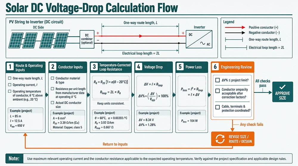
05 Apply the Formula in a Controlled Sequence
CONTROLLED CALCULATION / SIX STEPS
For equal positive and negative lengths, Lpositive + Lnegative becomes 2 × L. Do not add the factor of two again if the supplied length is already total circuit length.
06 Worked Example: 4 mm² vs 6 mm²
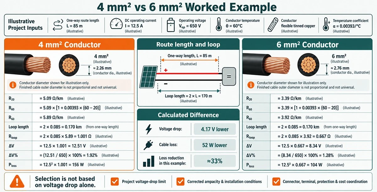
Assume 60 m one-way, 14 A, 800 V operating voltage and, for a screening comparison only, SINELINK page values at 20°C: 5.09 Ω/km for 4 mm² and 3.39 Ω/km for 6 mm². The 4 mm² loop resistance is 0.6108 Ω, drop 8.5512 V, drop 1.069%, and loss 119.72 W. The 6 mm² loop resistance is 0.4068 Ω, drop 5.6952 V, drop 0.712%, and loss 79.73 W.
These numbers do not approve either size because temperature correction, installed ampacity, connector fit and the project criterion remain open. The example shows the method and the resistance-driven difference.
07 Handle Parallel Conductors and Unequal Routes
Parallel conductors require verified equal length, construction, routing, termination and current sharing. Calculate the equivalent resistance using the actual parallel arrangement; do not divide resistance by the number of paths unless equal sharing is justified.
When positive and negative routes differ, calculate each path separately. Add connection and device losses only if the project definition says they belong inside the cable-circuit loss budget.
08 Interpret the Result Commercially
A larger conductor reduces resistive loss but adds copper, weight, drum and installation cost. Translate watt loss into annual energy only with defensible irradiance, operating-current distribution, availability and energy-value assumptions.
Procurement should compare compliant alternatives using installed and life-cycle cost. A small calculated saving on one short lead may not justify upsizing; repeated long runs can produce a different answer.
09 Calculation QA and Approval
Check units, loop length, current case, voltage basis, resistance temperature and decimal places. Have another engineer reproduce the calculation from the recorded inputs. Recalculate after module, route, cable, grouping or connector changes.
Publish calculator outputs with assumptions and version control. A screenshot without formulas, input provenance or revision history is weak design evidence.
Continue the cluster journey through: high-temperature route assumptions; photovoltaic power station cable solution.
KEY TAKEAWAYS
- Start from controlled project inputs, not a catalogue shortcut.
- Keep product compliance, installed design and delivered-batch conformity as separate checks.
- Record assumptions, evidence and approving party.
- Freeze cable and interface details before production.
- Treat substitutions as controlled changes.
- Use the smallest or simplest option only after every required gate passes.
10 Frequently Asked Questions
What is the basic solar DC voltage-drop formula?
For equal outgoing and return paths, ΔV = 2 × L × I × R, using one-way length and resistance per unit length at the relevant temperature.
Why is the cable length doubled?
Current travels through both positive and negative conductors. Do not double again if your input is already total loop length.
Should I use open-circuit voltage?
Use the voltage basis required by the project performance method and state it. Maximum-voltage safety and operating voltage-drop checks serve different purposes.
What current should be used?
Use the operating or design current case defined by the project method. Document whether it is maximum-power current, another operating case or a specified conservative value.
Is 1% always the limit?
No. The allowable drop is a project design and economic criterion under the applicable requirements.
Does a lower voltage drop prove cable safety?
No. Ampacity, protection, insulation rating, environment, terminations and code compliance remain separate.
Can copper resistivity replace product resistance?
It can support early comparison, but controlled manufacturer maximum resistance is normally preferable for a final product-specific check.
How does temperature affect voltage drop?
Higher conductor temperature increases copper resistance and therefore drop and loss at the same current.
How should parallel cables be calculated?
Use the equivalent resistance of the verified arrangement and confirm equal current sharing and matching terminations.
When should the calculation be repeated?
After any change to circuit, module, current assumption, route, conductor, temperature, parallel arrangement or termination.
PROJECT REQUEST
Solar DC Cable Engineering and Quotation Support
Send the destination market, project specification, circuit data, route and environment, cable/connector proposal, required evidence, inspection scope, packing and delivery terms. SINELINK can return a product and quotation response for engineering review. Request technical data and a project quotation
11 Engineering Note
This article is educational design and procurement support. The purchased standards, approved product documents, local requirements, project calculations and responsible approval authority remain controlling.
Authoritative Sources and Technical References
[1] BSI. BS IEC 62548-1:2023 - PV arrays design requirements - Official scope or verification context; consult the complete applicable document.
[2] IEC. IEC 62930:2017 - Electric cables for photovoltaic systems - Official scope or verification context; consult the complete applicable document.
[3] IEC. IEC 60228:2023 - Conductors of insulated cables - Official scope or verification context; consult the complete applicable document.