

How Long Does Solar Cable Last? Lifespan, Inspection and Replacement Guide
Lifespan, Inspection and Replacement Guide
Solar cable does not have one guaranteed replacement age. Some EN 50618-oriented product documents state an expected service period of at least 25 years under defined normal-use conditions, but actual field life can be shorter or longer. Heat, UV exposure, moisture, movement, abrasion, cable support, connector quality and installation workmanship all matter. Replace cable when condition assessment, electrical testing, fault history or incompatibility shows that it can no longer perform safely and reliably - not merely because a calendar date has passed.
For new-project specification, begin with the solar DC cable selection guide. This page addresses the later lifecycle question: how should an owner, EPC or O&M team inspect installed cable and decide whether to monitor, repair or replace it?
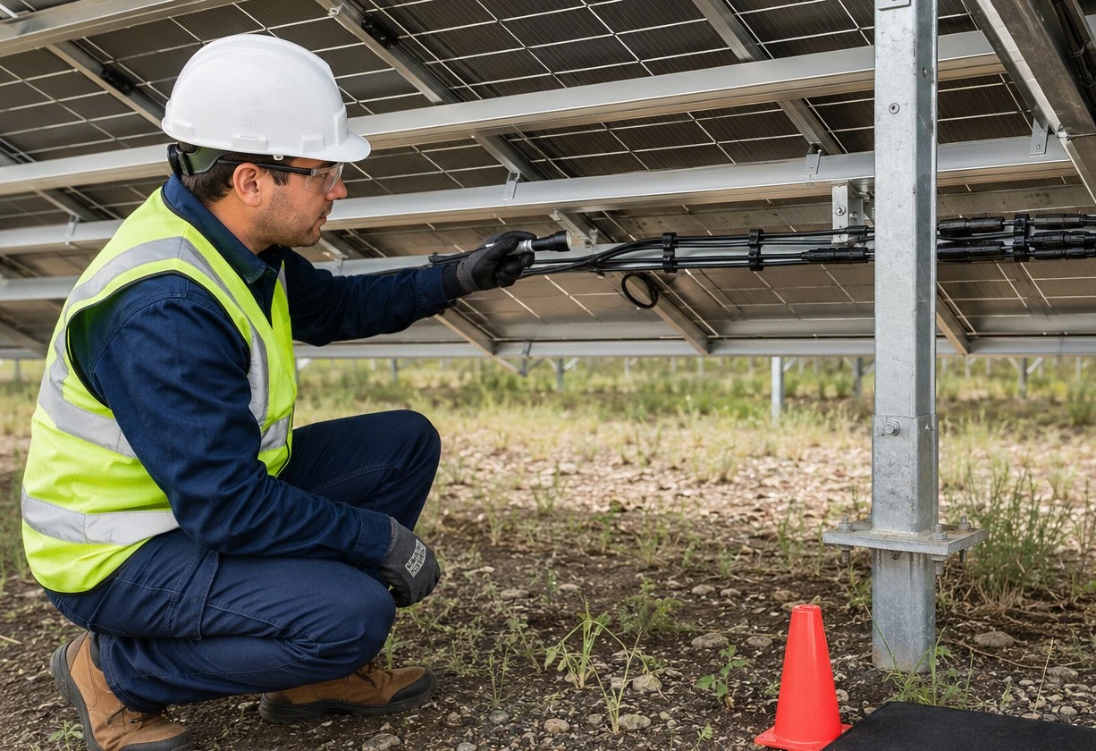
A useful lifespan plan separates four concepts: expected service life, design life, commercial warranty and actual condition. Treating them as interchangeable can create two opposite errors - replacing healthy cable too early or leaving visibly degraded cable in service because it has not reached a nominal age..
Expected Service Life, Design Life, Warranty and Actual Life
These terms answer different commercial and engineering questions. A product statement may describe expected use under specified conditions; a system designer may target a project life; a warranty defines contractual coverage; and the installed cable's actual condition reflects everything that happened during transport, installation and operation.
|
Term |
What it means |
What it does not prove |
Evidence to retain |
|
Expected service life |
Product-specific expectation under stated conditions |
An unconditional life for every site or installation |
Current datasheet and conditions |
|
Project design life |
Period considered in system design and lifecycle planning |
That every component will remain untouched for that period |
Design basis and O&M plan |
|
Commercial warranty |
Defined contractual remedy, term and exclusions |
The same thing as technical life |
Signed warranty and claim procedure |
|
Actual field life |
Time the installed cable remains safe and fit for service |
A fixed number known without inspection |
Asset history, inspection and test records |
As one product-specific example, LAPP states a 25-year expected service life for a particular H1Z2Z2-K-compliant application. That is useful evidence for that product and its stated conditions; it should not be copied into a claim about every EN 50618 cable, every SINELINK model or every installation.
What Shortens Solar Cable Life?
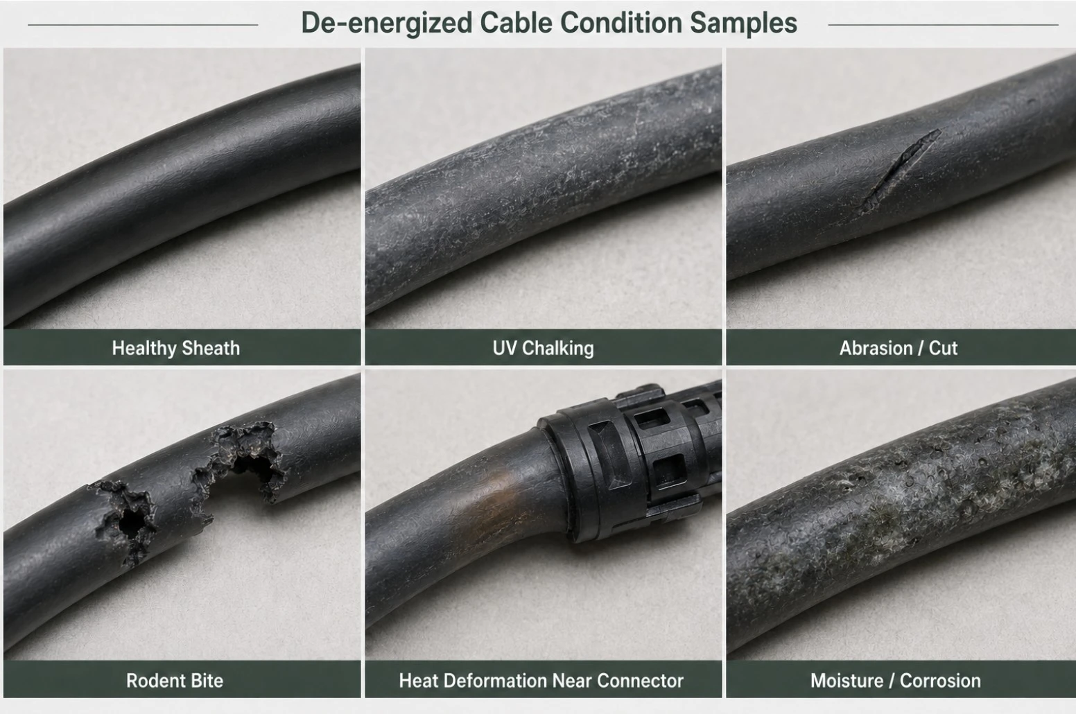
Cable aging is normally a combined-stress problem. The same cable construction can perform differently on a cool, well-managed ground-mount route and on a hot metal roof where unsupported cable rubs against sharp edges.
|
Stress |
Typical mechanism |
What an inspector may observe |
Control |
|
Heat and current |
Thermal aging; local overheating at high-resistance points |
Discoloration, hardening, deformation or hot connections |
Correct sizing, grouping and ventilation |
|
UV and weather |
Sheath aging from long outdoor exposure |
Fading, chalking, cracking or loss of flexibility |
Verified outdoor cable and correct routing |
|
Movement and abrasion |
Wind, trackers or thermal cycling rub cable on structures |
Polished spots, cuts, exposed insulation or conductor |
Clips, guards, bend control and slack management |
|
Water and chemicals |
Moisture entry or incompatible environmental exposure |
Swelling, corrosion, tracking or repeated insulation faults |
Correct product and sealed/protected route |
|
Poor support |
Sagging cable contacts roofs, soil or sharp edges |
Pinching, tight bends, hanging connectors or damaged ties |
Durable wire-management system |
|
Rodents and impact |
Bites, crushing, tools, vehicles or maintenance damage |
Punctures, tooth marks, flattened or severed cable |
Route protection and site controls |
|
Connection defects |
Incorrect contact, crimp, seal or cross-mating creates resistance/ingress |
Heat marks, melted bodies, corrosion or intermittent faults |
Approved interface and assembly process |
Dedicated PV cable is designed for the application, but construction alone cannot compensate for poor routing. Review PV cable vs normal cable when an installed route contains unidentified general-purpose wire or an unapproved substitution.
Cable, Connector and Support System Age Together
A PV string circuit is an assembly, not an isolated length of cable. The cable sheath, conductor, contacts, connector seals, junction-box entries, clips, ties, trays, conduit and equipment terminations influence one another. A failed tie can allow a cable to abrade; a poor crimp can create localized heat; a damaged seal can admit moisture; an unsupported connector can transfer mechanical load into the cable.
When heat, corrosion or intermittent faults appear near a field connection, use the solar cable and connector compatibility checklist to review cable size, outer diameter, conductor construction, contact, seal, tooling and mating family. Do not solve a connector defect by replacing only the visible cable segment without finding the cause.
The U.S. Department of Energy notes that standard plastic cable ties can fail prematurely from heat, UV exposure and chemical reactivity. Once support fails, slack cable may abrade surfaces, creating faults, performance loss and additional replacement work. Wire-management hardware therefore belongs in the cable-life inspection, not in a separate cosmetic checklist.
When Should Solar Cable Be Inspected?
Inspection frequency should be risk-based and written into the project O&M plan. IEC 62446-2 covers preventive, corrective and performance-related maintenance for grid-connected PV systems, including components and connections. The applicable local rules, owner requirements and manufacturer instructions determine the final program.
|
Inspection trigger |
Purpose |
Examples of scope |
|
Commissioning baseline |
Record as-built condition before long-term operation |
Route, support, marking, connector family, photos and test results |
|
Scheduled preventive inspection |
Find gradual degradation before a fault |
Accessible cables, supports, entries, connectors, enclosures and records |
|
Post-storm or external event |
Find damage from wind, hail, flood, fire, animals or site work |
Loose cable, impact, water, debris, exposed conductor and enclosure damage |
|
Fault-triggered inspection |
Locate the cause of ground, insulation, arc or repeated inverter alarms |
Affected circuit plus adjacent routes and terminations |
|
Modification or repowering |
Confirm old and new components form an approved system |
Voltage/current, size, connector family, route and documentation |
|
End-of-warranty or asset transaction |
Establish condition and replacement reserve |
Risk-ranked sample, fault history, inaccessible-route assumptions and budget |
Solar Cable Visual Inspection Checklist
Only trained and authorized personnel should inspect energized PV systems. Follow the site's electrical-safety procedure, isolation method and applicable requirements. Visual inspection does not establish that a circuit is electrically safe.
- Compare the installed route with current as-built drawings and cable schedules.
- Check identification, polarity, cable designation, size and visible production marking.
- Look for cuts, cracking, chalking, swelling, flattening, exposed insulation or conductor.
- Check abrasion at module frames, roof surfaces, tracker points, tray edges and penetrations.
- Confirm clips, ties, guards and supports remain secure, compatible and correctly spaced.
- Inspect bend radius, slack, tension and the load transferred to connectors or equipment entries.
- Look for discoloration, melted parts, odor, soot or other evidence of overheating or arcing.
- Check connector bodies, caps, seals, glands and junction entries for damage, separation or water entry.
- Review underground transitions, conduit, drainage and exposed risers for movement or physical damage.
- Record defects with circuit ID, location, photographs, severity, action owner and closeout evidence.
For buried routes and wet conduit, apply the additional checks in direct burial vs conduit for solar cable. An inaccessible cable should not be declared healthy merely because no damage is visible at the endpoints.
Warning Signs: Monitor, Plan Replacement or Act Immediately
The response depends on risk, not appearance alone. A cosmetic color change may require documentation and closer observation, while exposed conductor, heat damage, arcing evidence or repeated protection trips can require immediate isolation under the site's safety procedure.
|
Triage |
Examples |
Typical next step |
|
Act immediately |
Exposed conductor; burning or melting; arcing evidence; active water entry; severe crushing; repeated ground/arc fault |
Follow emergency/isolation procedure; qualified assessment; repair or replacement before return to service |
|
Plan corrective work |
Localized sheath damage; failed support; corrosion; connector heat signature; non-compliant mixed interface; recurring intermittent fault |
Define affected scope, root cause, approved materials, outage and verification |
|
Monitor and document |
Minor surface change with no confirmed loss of function and no safety defect |
Photograph, identify, trend and set a justified reinspection trigger |
What Electrical Tests Support a Replacement Decision?
Testing should be selected and performed by qualified personnel using the applicable project procedure and instrument requirements. No single test provides a universal remaining-life number for a low-voltage PV cable. Results are interpreted with visual condition, baseline data, circuit history and the installed configuration.
- Continuity and polarity checks help confirm circuit identity and gross connection problems.
- Insulation-resistance or other approved insulation tests can support fault investigation, but test voltage, connected equipment and safe isolation must be controlled.
- String current, voltage and performance comparison can identify an underperforming or open circuit but may not locate the physical defect.
- Thermography can identify abnormal heating at accessible connections when performed under suitable operating conditions.
- Connector/contact resistance or approved diagnostic methods can support investigation of high-resistance interfaces.
- Fault logs, inverter alarms and repeated protection operation provide important trigger and location evidence.
NREL's PV O&M guidance emphasizes keeping wires secure and protected, correcting ground and arc faults, and increasing inspection, testing and replacement where movement or rubbing is allowed. Testing results should therefore lead to root-cause correction, not only a splice at the first damaged point.
Repair One Section or Replace the Complete Run?
Localized repair may be technically possible in some systems, but the team must decide whether the defect is isolated or evidence of a route-wide problem. Adding a joint can introduce a new interface, documentation requirement and future inspection point.
|
Decision question |
Localized corrective action may be considered when |
Broader replacement is more likely when |
|
Extent |
Damage is isolated and the remaining route is verified |
Similar degradation appears across the route or batch |
|
Root cause |
External cause is understood and removed |
Heat, UV, movement, water or incompatibility remains systemic |
|
Interfaces |
An approved accessible repair/termination method exists |
Repair would create buried, inaccessible or unapproved joints |
|
Evidence |
Cable identity, rating and records are clear |
Cable is unidentified, counterfeit, undocumented or outside project requirements |
|
Economics |
Access is easy and outage impact is limited |
Repeated callouts, difficult access or future failures make partial work uneconomic |
|
Modification |
Circuit conditions are unchanged |
Repowering changes voltage, current, connector or route requirements |
After severe weather or visible damage, render the affected system safe and complete inspection and electrical testing before return to service. The DOE PV lifecycle guidance recommends planning corrective actions and repair costs rather than repeatedly resetting a tripped system without finding the fault.
How to Specify Replacement Solar Cable
Replacement is not a like-for-like color match. The new cable must suit the current system, route, connected components and destination-market requirements. Repowering, higher-current modules, changed inverters or new connectors can make the original specification obsolete.
- Identify the exact circuit, one-way route length, installation method and environmental exposure.
- Confirm maximum system voltage, design current, fault/protection requirements and voltage-drop target.
- Recalculate conductor size and thermal corrections for the present route and cable grouping.
- Match the connector, contact, seal, gland, terminal and approved mating family.
- Define the required cable standard, certification/listing, size coverage, marking and product evidence.
- Specify reel/coil length, colour, traceability, sample approval, inspection and test documents.
- Plan removal, installation, termination, testing, labeling, photographs and as-built record updates.
If the old 4mm² route is being reconsidered as 6mm², use the engineering boundary in 4mm² vs 6mm² solar cable; do not upsize without checking connector and gland compatibility.
Before approving the replacement product, follow how to verify a solar cable certificate and confirm that the exact model and ordered size are inside the current evidence scope.
For an EN-oriented replacement specification, review the current EN 50618 H1Z2Z2-K solar cable page, then request the exact datasheet, certificate, outer diameter, marking and permitted installation method for the offered model.
How to Extend Solar Cable Service Life
- Select cable and accessories for the actual voltage, temperature, UV, water, chemical, fire and installation conditions.
- Use a durable wire-management system that prevents sagging, rubbing, pinching and excessive connector load.
- Respect minimum bend radius, pulling force, installation temperature and manufacturer instructions.
- Use approved contacts, seals, tooling and mating combinations; document field assembly quality.
- Protect routes at edges, penetrations, vehicle crossings, tracker movement points and underground transitions.
- Create commissioning photographs and baseline electrical records for future comparison.
- Inspect after severe weather, external work, animal damage, alarms or unexplained performance loss.
- Close defects with root-cause action and update the asset register, not only a temporary patch.
For projects that need a coordinated cable schedule rather than isolated replacement lines, connect the lifecycle plan to the PV power station cable solution. This helps align string cable, connectors, route protection, documentation and spares.
Solar Cable Condition and Replacement RFQ Checklist
- Project country, commissioning year, system voltage and installed capacity.
- Affected circuit IDs, cable routes, lengths, installation method and accessibility.
- Existing cable markings, size, standard, manufacturer, batch and connector family.
- Photographs of damage, supports, transitions, connectors and equipment entries.
- Fault history, inverter alarms, inspection findings and available test results.
- Environmental conditions: roof temperature, UV, water, chemicals, rodents, wind or tracker movement.
- Proposed replacement size, required standard/listing, colour, outer diameter and installation method.
- Required reel lengths, preassembled leads, connectors, labels, spares, packaging and delivery schedule.
- Document package, inspection, sample approval, traceability and warranty requirements.
Request a Solar Cable Condition and Replacement Review
Send the route drawing, cable marking, connector information, photographs, fault history, test records and destination-market requirements. SINELINK can help organize the replacement-cable specification and required supply evidence. The site owner and qualified project professionals remain responsible for system isolation, inspection, testing and final return-to-service decisions.
Request a Solar Cable Condition & Replacement Review.
Frequently Asked Questions
How many years does solar cable last?
There is no universal guaranteed number. Some product documents state an expected period of at least 25 years under defined conditions, but actual life depends on the exact product, installation, environment, loading, connectors and maintenance.
Does a 25-year expected life mean a 25-year warranty?
No. Expected service life is a technical/product statement under stated conditions. Warranty coverage is a separate commercial agreement with its own term, remedy and exclusions.
Should all solar cable be replaced after 25 years?
Not automatically. Use the project plan, product documentation, condition inspection, fault history and applicable testing to determine whether cable remains fit for service.
What are the clearest signs that PV cable needs replacement?
Exposed conductor, severe cuts, burning, melting, arcing evidence, recurring insulation or ground faults, severe crushing, water-related damage and route-wide cracking require urgent qualified assessment.
Can cracked solar cable be repaired with electrical tape?
Tape should not be treated as a universal permanent repair. The damage, cable system, environment and approved repair method must be assessed; replacement may be required.
How often should solar cable be inspected?
Use a risk-based schedule defined by the O&M plan, applicable requirements and manufacturer instructions. Add inspections after storms, flooding, fire, site work, animal damage, alarms, faults and system modification.
Can an insulation-resistance test prove the remaining cable life?
No single test gives a universal remaining-life value. Interpret approved test results with visual condition, baseline data, circuit history, product information and route conditions.
Should connectors be replaced when cable is replaced?
Review the complete interface. Reuse is appropriate only when the connector system, contacts, seals, condition, rating, installation instructions and project requirements support it.
What records should be kept after replacement?
Keep removed-cable findings, root cause, product evidence, batch and reel data, assembly information, test results, photographs, labels, updated drawings and warranty documents.
Technical References
IEC 62446-2:2020 - Maintenance of grid-connected PV systems - Official IEC standard record.
IEC 62930:2017 - Electric cables for photovoltaic systems - Official IEC product-standard record.
NREL - Best Practices for Operation and Maintenance of Photovoltaic and Energy Storage Systems - Official technical report.
U.S. DOE - Operate and Maintain an Existing Photovoltaic System - Official lifecycle and O&M guidance.
U.S. DOE - Solar Photovoltaic Cable Management Best Practices - Official cable-management guidance.
NREL - Installation, Operations, and Maintenance resilience guidance - Official report containing PV wiring inspection prompts.
LAPP - ÖLFLEX SOLAR H1 BUR product page - Product-specific service-life example; not a universal claim.