


1500V DC | Tinned Copper | XLPO Insulation and Sheath
This ant-resistant PV cable combines a stranded tinned copper conductor with electron-beam cross-linked XLPO insulation, a Nylon 12 protective layer and an XLPO outer sheath.
Designed for photovoltaic DC connections rated at 1500V, its multilayer construction adds a protective barrier for installations where ant damage is a concern. Available conductor sizes include 4, 6 and 10 mm².
Rated voltage
Conductor sizes
Rated temperature range
Key Features

Nylon 12 Protective Barrier
A dedicated Nylon 12 layer sits between the XLPO insulation and outer sheath, adding protection against ant-related damage.

Stranded Tinned Copper
The conductor combines copper conductivity with a protective tin coating. Its stranded construction supports routing and termination during installation.

Electron Beam Cross Linked XLPO
XLPO insulation provides electrical separation around the conductor, while the XLPO outer sheath protects the underlying layers.

UV Resistance
The UV-resistant construction supports outdoor PV applications where cables are exposed to sunlight.

Mechanical Protection
The additional Nylon 12 layer complements the outer sheath, providing a further barrier around the insulated conductor.

1500V DC Rating
Designed for photovoltaic DC circuits with a rated voltage of 1500V. Final selection should account for maximum circuit voltage, current, installation conditions and termination requirements.
Understanding the Nylon 12 Protective Layer
What Is Nylon 12
Nylon 12, also known as polyamide 12 or PA12, is an engineering thermoplastic used in cable protection and other demanding applications. It offers a useful combination of toughness, abrasion resistance and low moisture absorption. Its relatively low water uptake helps maintain dimensional stability as humidity changes.
Why Use It for Ant Protection
Selected PA12 cable compounds are used for their resistance to ant and termite attack. Their mechanical properties make them useful as protective barriers around vulnerable cable layers. These material properties explain the choice of Nylon 12 for this cable's additional protection layer. [2]
Actual resistance depends on the PA12 grade, layer thickness, manufacturing quality, insect species and exposure conditions. Material-level performance does not automatically establish a finished cable's resistance to every pest.
How the Layers Work Together
|
Layer
|
Material
|
Main Function
|
|---|---|---|
|
Conductor
|
Stranded tinned copper
|
Carries DC electrical current
|
|
Insulation
|
Electron-beam cross-linked XLPO
|
Provides electrical insulation around the conductor
|
|
Intermediate protective layer
|
Nylon 12
|
Adds a barrier against ant-related damage
|
|
Outer sheath
|
Electron-beam cross-linked XLPO
|
Protects the underlying layers from external exposure
|
The Nylon 12 layer supplements the cable's insulation and sheath. Installation protection, cable support and suitable terminations remain essential.
Technical Specifications
*The +120°C and +250°C values represent separate conductor temperature limits, not the normal rated temperature range. Applicable exposure durations and operating conditions must be confirmed against the approved product specification.
Cable Dimensions and Conductor Resistance
|
Nominal Cross-Section (mm²)
|
Conductor Construction (No. × mm)
|
Cable Outside Diameter (mm)
|
Max. DC Resistance at 20°C (Ω/km)
|
|---|---|---|---|
|
4
|
56 × 0.285
|
6.20
|
5.09
|
|
6
|
84 × 0.285
|
7.20
|
3.39
|
|
10
|
142 × 0.285
|
8.40
|
1.95
|
Layer Thicknesses
Thickness values apply to the listed sizes. Final dimensions and tolerances are subject to the approved product datasheet.
Manufacturing Capabilities
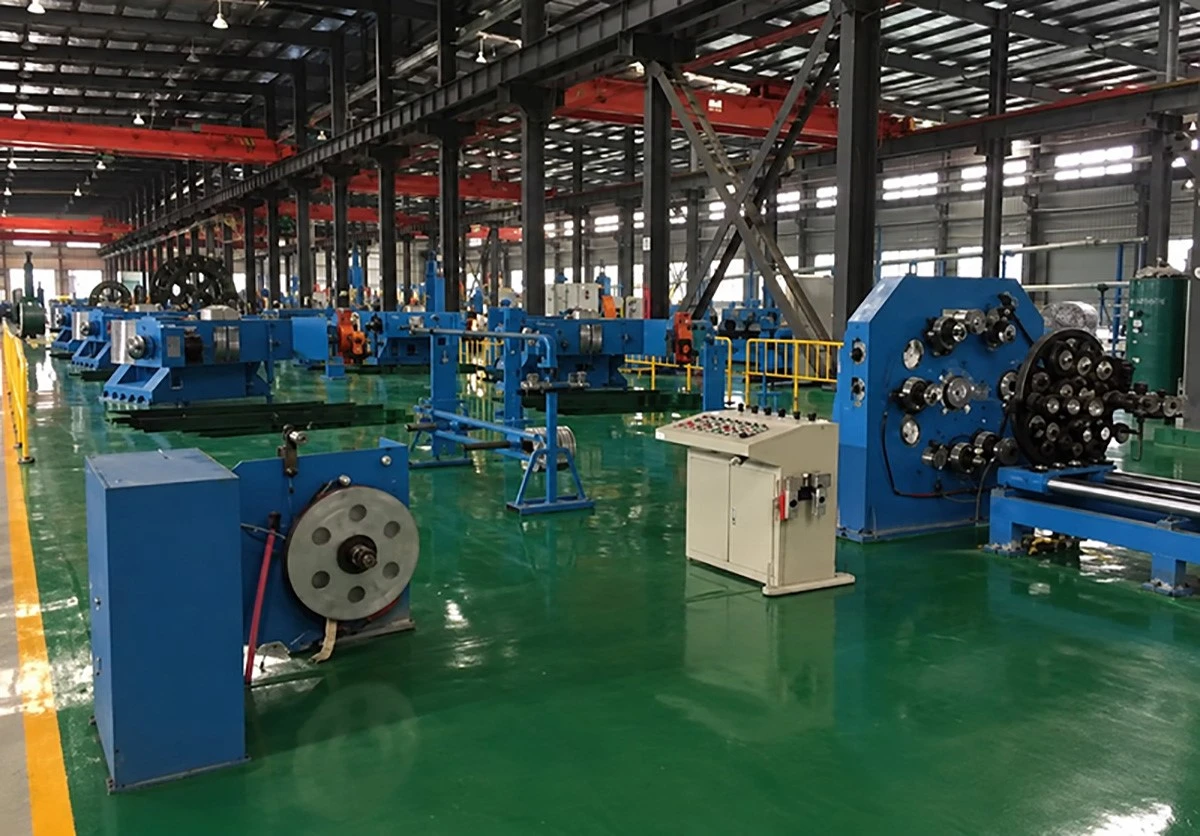
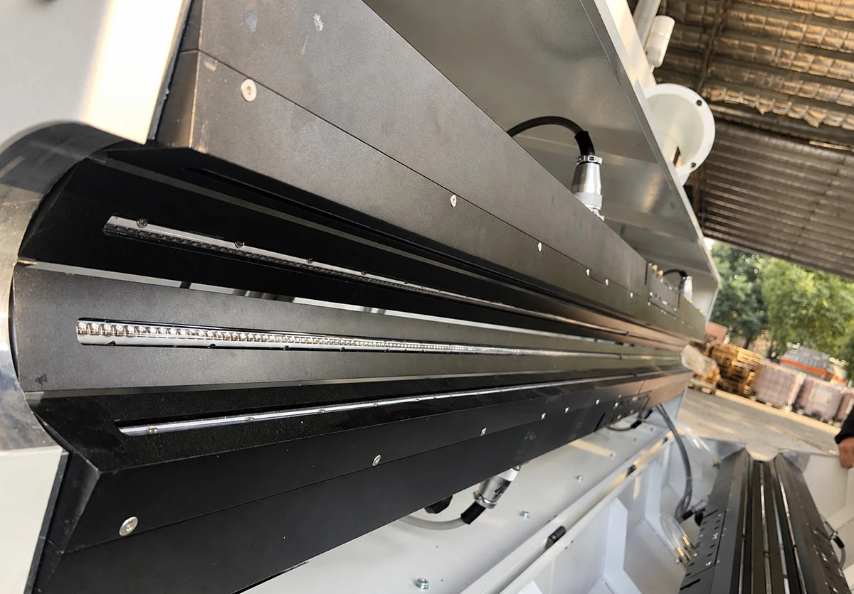
SINELINK works with cable manufacturing partners to coordinate product specifications, production requirements and delivery. For this ant-resistant PV cable, manufacturing control centres on conductor construction, layer consistency and the integrity of the Nylon 12 protective barrier.
Quality Assurance
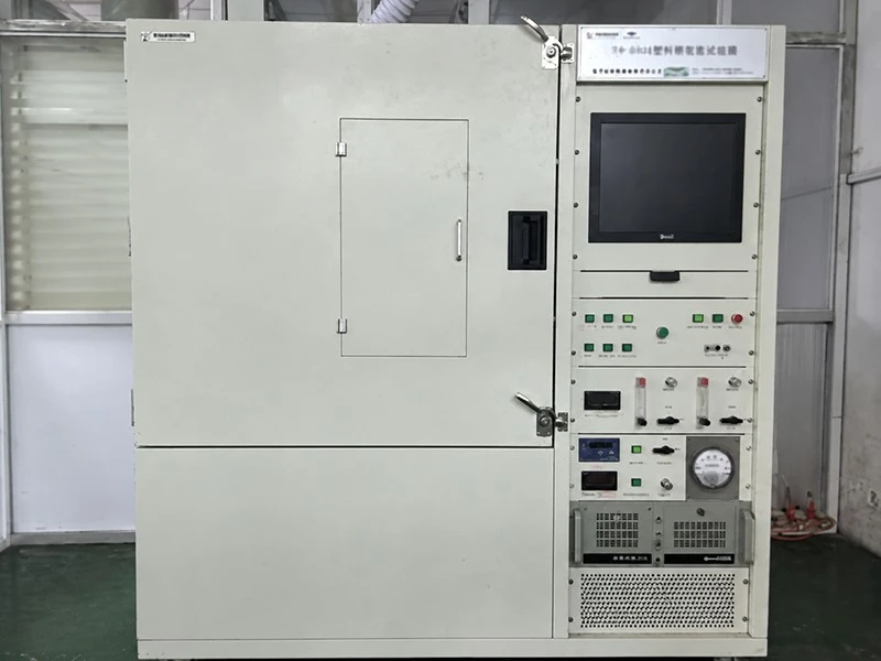
Quality requirements are agreed against the approved cable specification. Review covers construction dimensions, appearance, electrical performance and the supporting records required for the order. Any project-specific ant-resistance tests should be defined separately.

Order Records and Traceability
Order documentation can be agreed to include product identification, inspection records, packing details and relevant test or certification documents. Cable marking and batch information should remain consistent with the approved order specification.
Standards and Testing

Reference Standards
Reference Standards
Fire Test Reference
For technical approval, contact SINELINK to confirm the applicable certificates and test reports for the selected cable construction and size.
Where ant resistance is a project requirement, specify the target pest, test method and acceptance criteria. General PV cable compliance should be reviewed separately from evidence of pest resistance.
Applications
Intended applications include:
Ground-Mounted PV
Ground-mounted photovoltaic installations.
Commercial & Industrial Rooftops
Commercial and industrial rooftop PV systems.
PV Strings & Combiner Boxes
PV string connections and DC wiring to combiner boxes.
Locations with Ant-Damage Concerns
Solar installations in locations where ant damage has been identified as a cable protection concern.
Cable routing should account for mechanical damage, moisture, temperature, bending limits and maintenance access. Underground or direct-burial use requires separate confirmation of the cable's approved installation scope.
Specify Additional Protection for Your PV Project
Send SINELINK your required conductor size, quantity, system voltage and installation method. If ant resistance is part of the project specification, include the target pest and any required testing or approval criteria.
We will help you review the cable specification and prepare a quotation for your application.
Ant-Resistant PV Cable · Nylon 12 Protection
Technical Specifications
*The +120°C and +250°C values represent separate conductor temperature limits, not the normal rated temperature range. Applicable exposure durations and operating conditions must be confirmed against the approved product specification.
Cable Dimensions and Conductor Resistance
|
Nominal Cross-Section (mm²)
|
Conductor Construction (No. × mm)
|
Cable Outside Diameter (mm)
|
Max. DC Resistance at 20°C (Ω/km)
|
|---|---|---|---|
|
4
|
56 × 0.285
|
6.20
|
5.09
|
|
6
|
84 × 0.285
|
7.20
|
3.39
|
|
10
|
142 × 0.285
|
8.40
|
1.95
|
Layer Thicknesses


