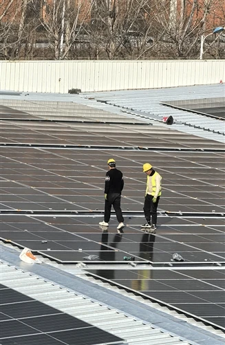
A high-quality PV system depends not only on modules and inverters, but also on low-loss, stable and weather-resistant transmission components. Poor cable sizing, low-grade insulation, high connector contact resistance or improper installation can lead to power loss, overheating, water ingress, arcing, downtime and higher maintenance costs.
1. Cable Quality Determines Transmission Loss and Service Life
Cable selection should focus on conductor material, resistance, temperature rating, insulation performance, UV resistance and environmental adaptability. Lower resistance reduces line loss, while durable insulation protects the system from aging, cracking and leakage current.
| Parameter | High-Quality Copper Cable | Standard Copper Cable | Aluminum Alloy Cable | Engineering Impact |
|---|---|---|---|---|
| Conductivity | approx. 63 MS/m | approx. 58 MS/m | approx. 36-38 MS/m | Higher conductivity reduces line loss |
| Resistivity at 20°C | approx. 0.0167 Ω·mm²/m | approx. 0.0185 Ω·mm²/m | approx. 0.028-0.032 Ω·mm²/m | Aluminum alloy requires larger cross-section |
| Temperature coefficient | approx. 0.00385/°C | approx. 0.00403/°C | approx. 0.00422/°C | Resistance rises as temperature increases |
| Density | approx. 8.89 g/cm³ | approx. 8.89 g/cm³ | approx. 3.63 g/cm³ | Aluminum alloy is much lighter |
| Typical advantage | Low loss | Mature solution | Lower weight and cost | Selection depends on distance, current and site conditions |
For long-distance transmission, cable resistance becomes especially important. In high-temperature environments, resistance increases further, which can reduce system efficiency. In harsh outdoor environments such as deserts, coastal areas and high-altitude sites, cable sheath and insulation quality also determine whether the system can remain stable over years of operation.
2. Connector Quality Affects Safety More Directly
Connectors are one of the most failure-sensitive points in PV systems. Their contact resistance, waterproof rating, locking structure and brand compatibility directly affect heat generation and failure risk.
| Connector Type | Typical Contact Resistance | Protection Rating | Current-Carrying Capability | Suitable Applications |
|---|---|---|---|---|
| Standard MC4 | 0.25-0.35 mΩ | IP67 | Medium | Small and medium PV systems |
| MC4-EVO2 | approx. 0.2 mΩ | IP67 | High, suitable for 1500V systems | High-power PV systems |
| T4 Connector | ≤0.25 mΩ | IP68 | Relatively high | Utility-scale and harsh environments |
| Basic copper-aluminum connector | ≤0.5 mΩ | IP68 | Medium | Special environments, depending on design |
Higher contact resistance means higher heat and higher power loss. For example, under 100A current, every 1 mΩ of contact resistance can generate about 10W of heat loss at a single connection point. In a large PV plant with thousands of connection points, this can become a serious efficiency and safety issue.
Poor connector matching is another common risk. Mixing connectors from different brands may cause tolerance mismatch, unstable contact pressure, water ingress or arcing. Certified and compatible connectors should always be used as a complete system.
3. Poor Selection Increases Power Loss and O&M Cost
The document highlights several project-level impacts:
| Issue | Direct Result | Long-Term Impact |
|---|---|---|
| High cable resistance | Higher DC line loss | Lower annual energy yield |
| Poor insulation or sheath aging | Cracking, leakage or short circuit risk | Frequent replacement and downtime |
| High connector contact resistance | Local overheating | Efficiency loss and fire risk |
| Low waterproof rating | Water and dust ingress | Corrosion, poor contact and failure |
| Improper crimping or installation | Loose connection | Arc fault and unstable operation |
| Ignoring site environment | Product aging faster than expected | Higher lifetime maintenance cost |
From a life-cycle perspective, low-cost components may save 5-10% in initial procurement, but they can create much higher losses after 2-3 years of operation. Quality cables and connectors reduce energy loss, improve system availability and lower maintenance frequency over the full 25-year project life.
4. Selection Should Match the Project Environment
| Project Scenario | Cable Selection Focus | Connector Selection Focus |
|---|---|---|
| High altitude | Larger safety margin, strong insulation, low-temperature flexibility | IP68, wide temperature range, stable contact resistance |
| Coastal / salt-spray area | Tinned copper or corrosion-resistant conductor | Salt-spray resistance, strong sealing, corrosion-resistant terminals |
| Desert / high temperature | High-temperature sheath, UV resistance, proper derating | Low contact resistance, high temperature rating |
| Short-distance / high-precision system | Low-resistance copper cable | Certified connector with reliable crimping |
| Large utility-scale plant | Optimized cross-section and life-cycle cost | High-current, low-resistance, certified connector system |
5. Best Practices for PV Engineering
Use certified cables and connectors that comply with relevant standards such as CQC, TÜV, UL, IEC or project-specific requirements.
Avoid mixing connectors from different manufacturers unless compatibility is clearly verified.
Select cable size based on current, voltage drop, temperature, laying method and project distance.
Use professional crimping tools recommended by the connector manufacturer.
Keep the required bending radius during installation to avoid conductor or insulation damage.
Do not disconnect DC connectors under load, as this may cause arcing.
Inspect connectors and cables regularly for loosening, cracking, discoloration, overheating or water ingress.
Conclusion
Cable and connector selection is a small design decision with a large engineering impact. High-quality, properly matched and correctly installed components help reduce power loss, prevent overheating, improve system reliability and lower long-term O&M cost. For PV projects, reliable connection is not just a detail. It is the foundation of safe, stable and efficient power generation.